Work vehicle multi-coupler with breakaway feature

a multi-coupler and work vehicle technology, applied in the field of work vehicles, can solve the problems of stress and damage to the power lines and components of the work vehicle and implement, and achieve the effect of facilitating controlled disengagemen

Active Publication Date: 2018-05-15
DEERE & CO
View PDF15 Cites 3 Cited by
  • Summary
  • Abstract
  • Description
  • Claims
  • Application Information

AI Technical Summary

Benefits of technology

[0005]Work vehicle multi-coupler assemblies having controlled breakaway features are provided. In one embodiment, the work vehicle multi-coupler assembly includes a first bank of fluid connectors, a second bank of fluid connectors configured to matingly engage the first bank of fluid connectors along a coupling axis, and a coupler mechanism coupled to the first bank of fluid connectors. The coupler mechanism is controllable to bring the second bank of fluid connectors into mating engagement with the first bank of fluid connectors. A breakaway feature is integrated into the coupler mechanism and facilitates controlled disengagement of the first bank of fluid connectors from the second bank of fluid connectors along the coupling axis during a breakaway event, such as when a work implement inadvertently detaches from a tractor or other work vehicle. The breakaway feature permits controlled disengagement of the first and second banks of fluid connectors.
[0007]Embodiments of a work vehicle, such as a tractor, including a multi-coupler assembly are further provided. In one embodiment, the work vehicle is configured to be removably connected to an implement including an implement-side fluid connector bank, which is retained in an implement-side connector block. The implement-side connector block may include a guide, such as a laterally-projecting roller pin. In such an embodiment, the work vehicle may include a vehicle body and a multi-coupler assembly attached to the vehicle body. The multi-coupler assembly may include, in turn: (i) a vehicle-side fluid connector bank retained in a vehicle-side connector block and configured to matingly engage the implement-side fluid connector bank, (ii) a coupler mechanism rotatably coupled to the vehicle-side connector block and movable between a receiving position and a coupling position, and (iii) a breakaway feature including or assuming the form of an exit slot formed in the coupler mechanism. The coupler mechanism may have a guideway in which the guide may be received such that the coupler mechanism may be rotated to bring the implement-side fluid connector bank into mating engagement with the vehicle-side fluid connector bank. Additionally, the exit slot may intersect the guideway such that, when the coupler mechanism is in the coupling position, the guide is permitted to pass through the exit slot and thereby facilitate disengagement of the first and second banks of fluid connectors during breakaway of the implement from the vehicle body.

Problems solved by technology

Inadvertent separation of the implement from the work vehicle may stress and damage the power lines and components of the work vehicle and implement to which they are coupled.

Method used


Image

  • Work vehicle multi-coupler with breakaway feature
  • Work vehicle multi-coupler with breakaway feature
  • Work vehicle multi-coupler with breakaway feature

Examples


Embodiment Construction

[0018]The following describes one or more example embodiments of the disclosed multi-coupler assembly, as shown in the accompanying figures of the drawings described briefly above. Various modifications to the example embodiment(s) may be contemplated by one of skill in the art.

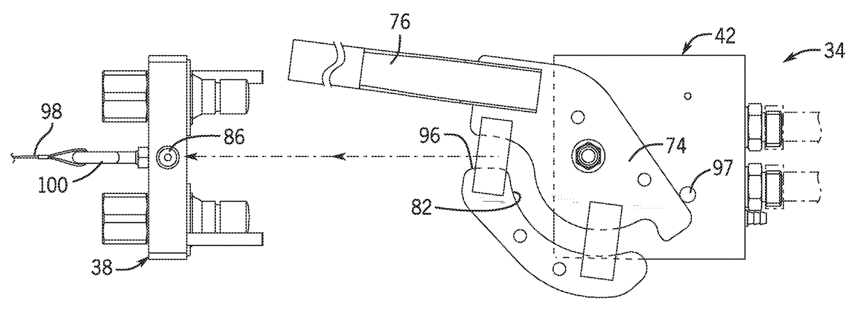
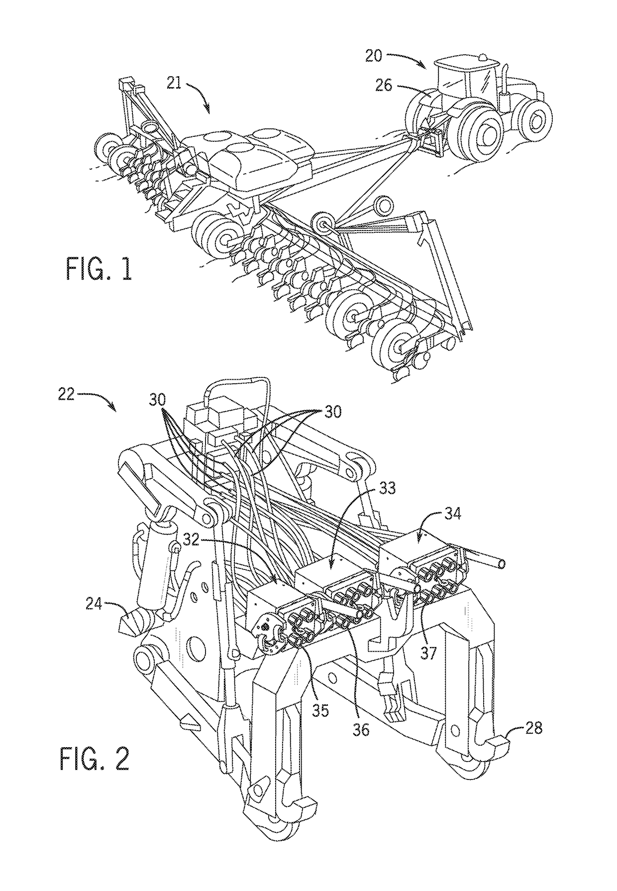
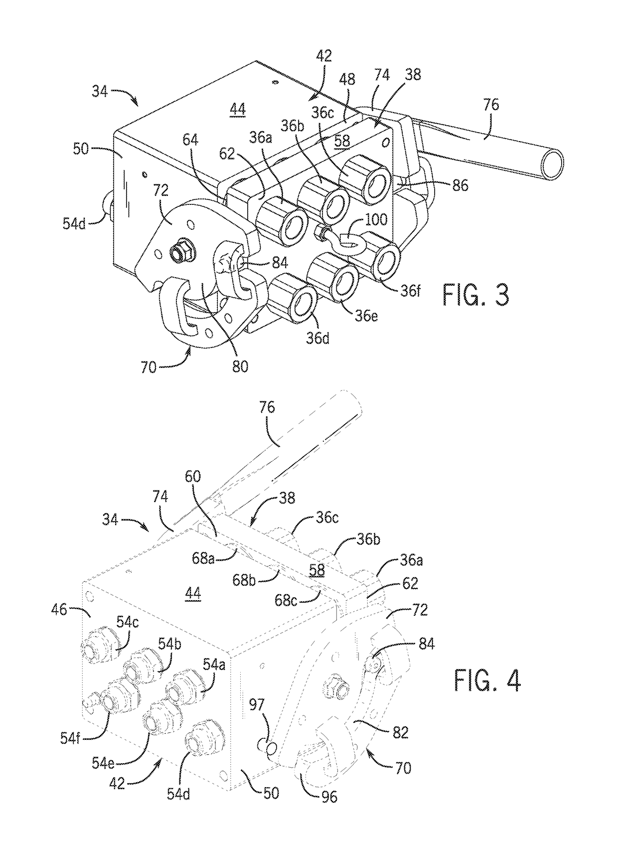
[0019]Specialized devices referred to as “multi-couplers” or “multi-coupler assemblies” enable multiple mating pairs of fluid lines to be quickly connected (or disconnected) when attaching a work implement to (or detaching the work implement from) a work vehicle. In so doing, a multi-coupler assembly may significantly reduce the amount of time required to attach and detach the work implement from the work vehicle, while helping to ensure that the fluid lines are coupled in a proper manner (e.g., such that fluid connectors of opposing polarities are appropriately joined). By conventional design, the multi-coupler assembly typically locks the mating pairs of fluid connectors in mating engagement. Disengagement ...


PUM


Abstract

A multi-coupler assembly for a work vehicle includes a first bank of fluid connectors, a second bank of fluid connectors configured to matingly engage the first bank of fluid connectors along a coupling axis, and a coupler mechanism coupled to the first bank of fluid connectors. The coupler mechanism is controllable to bring the second fluid connector bank into mating engagement with the first fluid connector bank. A breakaway feature is integrated into the coupler mechanism. The breakaway feature facilitates controlled disengagement of the first fluid connector bank from the second fluid connector bank along the coupling axis during a breakaway event, such as when an implement inadvertently detaches from the work vehicle. The breakaway feature may permit controlled disengagement of the first and second fluid connector banks without requiring movement of the coupler mechanism.

Description

CROSS-REFERENCE TO RELATED APPLICATION(S)[0001]Not applicable.STATEMENT OF FEDERALLY SPONSORED RESEARCH OR DEVELOPMENT[0002]Not applicable.FIELD OF THE DISCLOSURE[0003]This disclosure relates generally to work vehicles and, more particularly, to coupler assemblies that join fluid lines extending from a work vehicle to an implement attachment.BACKGROUND OF THE DISCLOSURE[0004]Work vehicles, such as those used in the agriculture, construction, forestry and mining industries, may have implements attached at the front and / or rear of the work vehicle. Example implements common in such industries include excavator and loader buckets, tillage machines, mowers, balers, planting machines, tree felling heads and so on. To perform operational movements (e.g., lifting, tool adjustment, baling, seeding, cutting, general orientation changes, etc.), the implements may have actuators (e.g., electric, hydraulic, pneumatic, etc.) that are powered by generators, pumps and motors that are driven by the...

Claims


Application Information

Patent Timeline
Patent Type & Authority Patents(United States)
IPC IPC(8): F16K17/40B60D1/28B60D1/24A01B59/042F16L35/00B60D1/64A01B61/02A01B59/043F16L37/56F16L55/10B60D1/00
CPCA01B59/042A01B59/043A01B61/025B60D1/243B60D1/64F16L35/00F16L37/56B60D1/28F16L55/1015B60D2001/008F16L37/18
Inventor EMMERT, ROBERT C.HOLLAND, MICHAEL A.SANDOVAL, FERNANDOREHN, NATHANAEL
Owner DEERE & CO
Why Eureka
Try Eureka