MRI-safe implantable lead assembly

a lead assembly and implantable technology, applied in the field of mri-safe implantable lead assemblies, can solve the problems of inducing electric current in parts of the system, dangerous current induced in the implantable lead assemblies by an electro-magnetic field of an mri procedure, and causing damage or discomfort, so as to mitigate the effects of current, dissipate induced current, and reduce curren

Active Publication Date: 2018-05-22
LIVANOVA USA INC
View PDF7 Cites 20 Cited by
  • Summary
  • Abstract
  • Description
  • Claims
  • Application Information

AI Technical Summary

Benefits of technology

[0004]Accordingly, an MRI-safe medical device system, lead, or component of the present disclosure may be configured to prevent or limit the formation of a current, to dissipate a current, and / or to mitigate the effects of a current induced in an implantable lead assembly or a component thereof by an electro-magnetic field of an MRI procedure. The medical device system, lead, or component may limit or avoid application of the induced current to the tissue of the patient. Additionally, the MRI-safe medical device system, lead, or component may be configured to dissipate induced current in a manner that limits formation of local hotspots as a result of Ohmic heating generated by a magnetic field.
[0009]The impedance threshold may be selected such that when exposed to the external electro-magnetic field at the first frequency or at the second frequency, the implantable lead assembly is able to safely dissipate the induced current without significant (e.g., greater than 2 degrees Celsius) localized heating. For example, the impedance threshold may be about 1 kOhm. Thus, in this example, the implantable lead assembly may have an impedance of about 1 kOhm with respect to a current induced by a 1.5 T MRI system and may have an impedance of about 1 kOhm with respect to a current induced by a 3 T MRI system. Accordingly, a patient with the implantable lead assembly may safely undergo a 1.5 T MRI procedure or a 3 T MRI procedure without removing the implantable lead assembly.
[0015]The impedance threshold may be selected such that when exposed to the external electro-magnetic field at the first frequency or at the second frequency (e.g., or any frequency between the first frequency and the second frequency), the medical device system is able to safely dissipate the induced current in the implantable lead assembly without significant (e.g., greater than 2 degrees Celsius) localized heating. For example, the impedance threshold may be about 1 kOhm. Thus, in this example, the filter and the implantable lead assembly may have a combined impedance of about 1 kOhm with respect to a current induced by a 1.5 T MRI system and may have a combined impedance of about 1 kOhm with respect to a current induced by a 3 T MRI system. Accordingly, a patient using the medical device system may safely undergo a 1.5 T MRI procedure or a 3 T MRI procedure without removing the implantable lead assembly and / or other components of the medical device system.
[0020]One particular advantage provided by at least one of the disclosed embodiments is that a patient with an implantable lead assembly may safely undergo a 1.5 T MRI procedure or a 3 T MRI procedure without removing the implantable lead assembly. For example, the implantable lead assembly may have an impedance of about 1 kOhm with respect to a current induced by a 1.5 T MRI system and may have an impedance of about 1 kOhm with respect to a current induced by a 3 T MRI system. At an impedance of about 1 kOhm, the implantable lead assembly may safely dissipate the induced current without significant (e.g., greater than 2 degrees Celsius) localized heating.

Problems solved by technology

However, an electro-magnetic field used during the MRI procedure can induce electric currents in portions of the system, such as the implantable lead assembly.
A current induced in an implantable lead assembly by an electro-magnetic field of an MRI procedure can be dangerous for the patient.
For example, if the current is applied to the tissue of the patient, the current can cause damage or discomfort.

Method used


Image

  • MRI-safe implantable lead assembly
  • MRI-safe implantable lead assembly
  • MRI-safe implantable lead assembly

Examples


Embodiment Construction

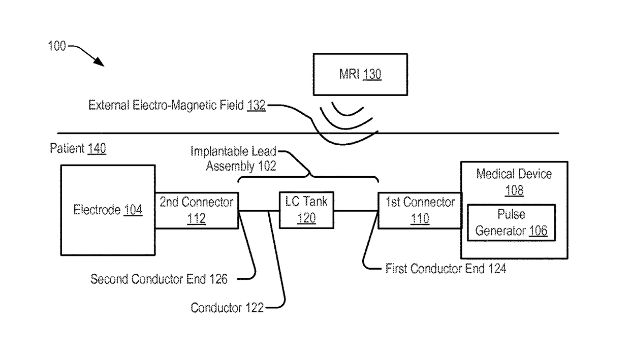
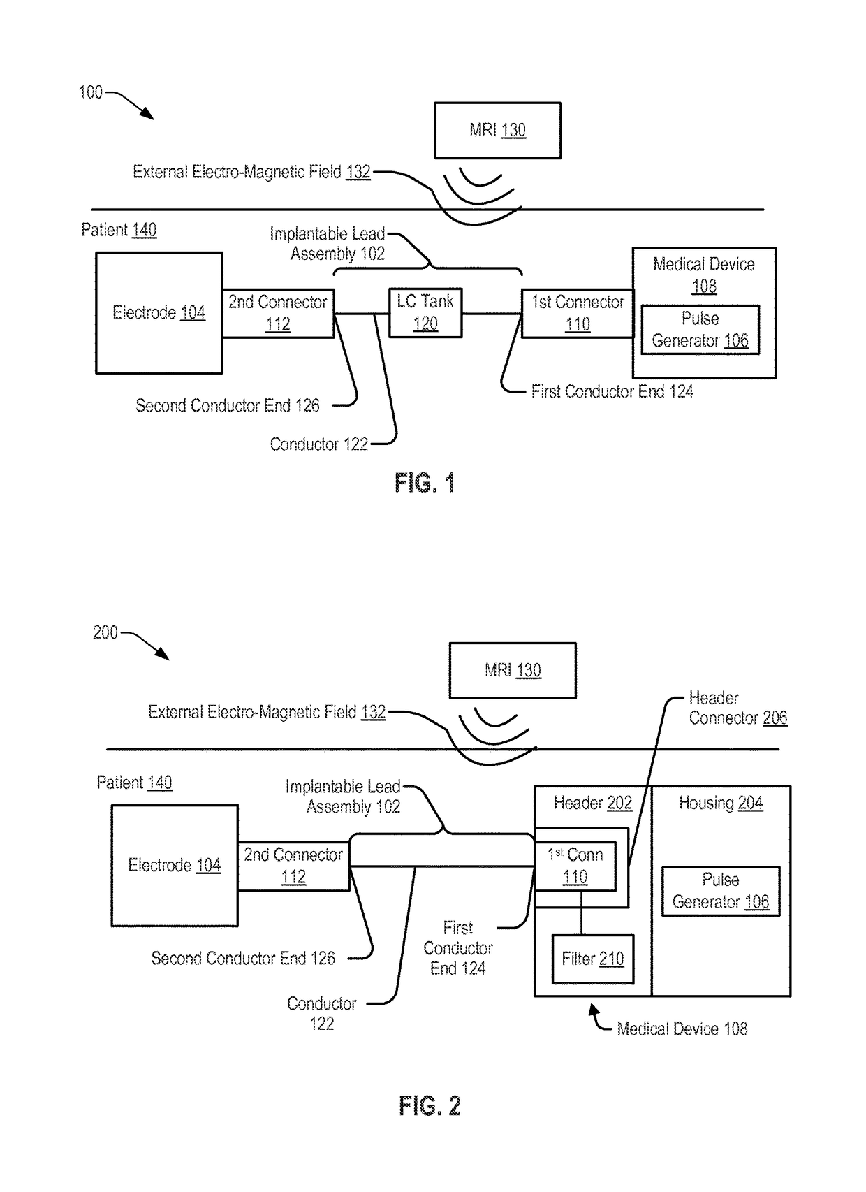
[0036]Referring to FIG. 1, a system 100 including an implantable lead assembly 102 is shown. The implantable lead assembly 102 may be coupled, via a first connector 110, to a medical device 108 and may be coupled, via a second connector 112, to an electrode 104. The implantable lead assembly 102 may include a conductor 122 extending from a first conductor end 124 to a second conductor end 126. The first conductor end 124 may be coupled, via the first connector 110, to the pulse generator 106. The second conductor end 126 may be coupled, via the second connector 112, to the electrode 104.

[0037]In a particular embodiment, the system 100, or a portion thereof, may be implanted within tissue of a patient 140 to provide therapy or to sense information from the tissue of the patient 140. For example, the electrode 104 may be configured to sense information related to tissue of a patient 140 (e.g., electrical signals generated by a nerve of the patient 140) and to provide the information t...


PUM


Abstract

A medical device includes a pulse generator and a filter. The pulse generator is configured to generate a stimulation signal and to provide the stimulation signal to tissue of a patient via an implantable lead assembly. The filter is configured to couple to the implantable lead assembly. A combined impedance of the implantable lead assembly and the filter with respect to a current induced by an external electro-magnetic field satisfies an impedance threshold when the external electro-magnetic field has a first frequency and when the external electro-magnetic field has a second frequency. The combined impedance has a peak impedance value when the external electro-magnetic field has a third frequency that is between the first frequency and the second frequency.

Description

FIELD OF THE DISCLOSURE[0001]The present disclosure is generally related to medical devices and implantable lead assemblies and, in particular, to medical devices and lead assemblies exposed to MRI fields.BACKGROUND[0002]Implantable lead assemblies, coupled to medical devices, are used for a variety of medical purposes, such as gathering patient body parameter data or providing therapy (e.g., electro-stimulation). For example, an implantable lead assembly may be used as part of a system that includes an electrode and a medical device (e.g., an implantable medical device or an external medical device). A surgical procedure may be used to implant at least a portion of the system within tissue of a patient, and removal of the system from the patient may require a second surgical procedure. Accordingly, removal of the system after implantation should be avoided to the extent possible.[0003]If the patient needs certain imaging procedures, such as a magnetic resonance imaging (MRI) proced...

Claims


Application Information

Patent Timeline
Patent Type & Authority Patents(United States)
IPC IPC(8): A61N1/08A61N1/365A61N1/375A61N1/02A61N1/05A61N1/37
CPCA61N1/08A61N1/025A61N1/05A61N1/3718A61N1/3752A61N1/3754A61N1/36521A61N1/086
Inventor THOMPSON, DAVID L.LINDH, JASON F.
Owner LIVANOVA USA INC
Why Eureka
Try Eureka