BUCK-type light emitting diode circuit

A light-emitting diode and circuit technology, applied in the electronic field, can solve problems affecting current stability, light-emitting diode current influence, etc., and achieve the effect of current stability

Active Publication Date: 2016-03-02
WUXI CHINA RESOURCES HUAJING MICROELECTRONICS
View PDF6 Cites 0 Cited by
  • Summary
  • Abstract
  • Description
  • Claims
  • Application Information

AI Technical Summary

Problems solved by technology

[0006] In view of this, the embodiment of the present invention provides a buck-type light-emitting diode circuit to solve the problem of buck-type light-emitting diode circuits in the prior art. When the AC voltage input by the power grid fluctuates or the ambient temperature fluctuates, the The current of the light-emitting diode has a large impact, thus affecting the technical problem of the stability of its current

Method used


Image

  • BUCK-type light emitting diode circuit
  • BUCK-type light emitting diode circuit
  • BUCK-type light emitting diode circuit

Examples


Embodiment Construction

[0029] The present invention will be further described in detail below in conjunction with the accompanying drawings and embodiments. It should be understood that the specific embodiments described here are only used to explain the present invention, but not to limit the present invention. In addition, it should be noted that, for the convenience of description, only parts related to the present invention are shown in the drawings but not all content.

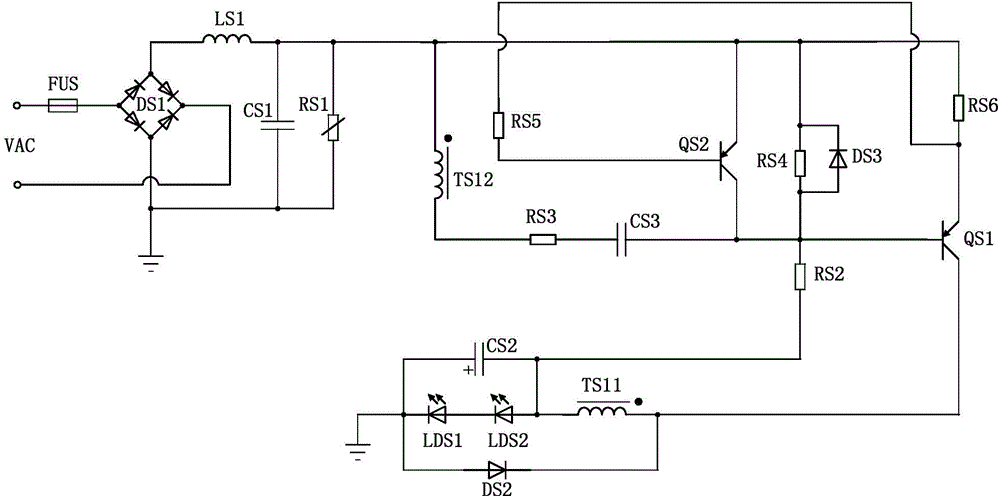
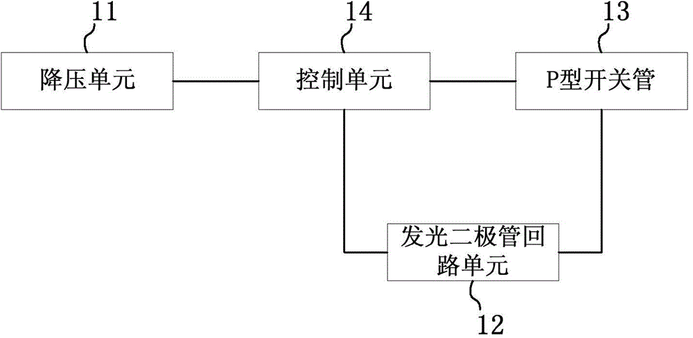
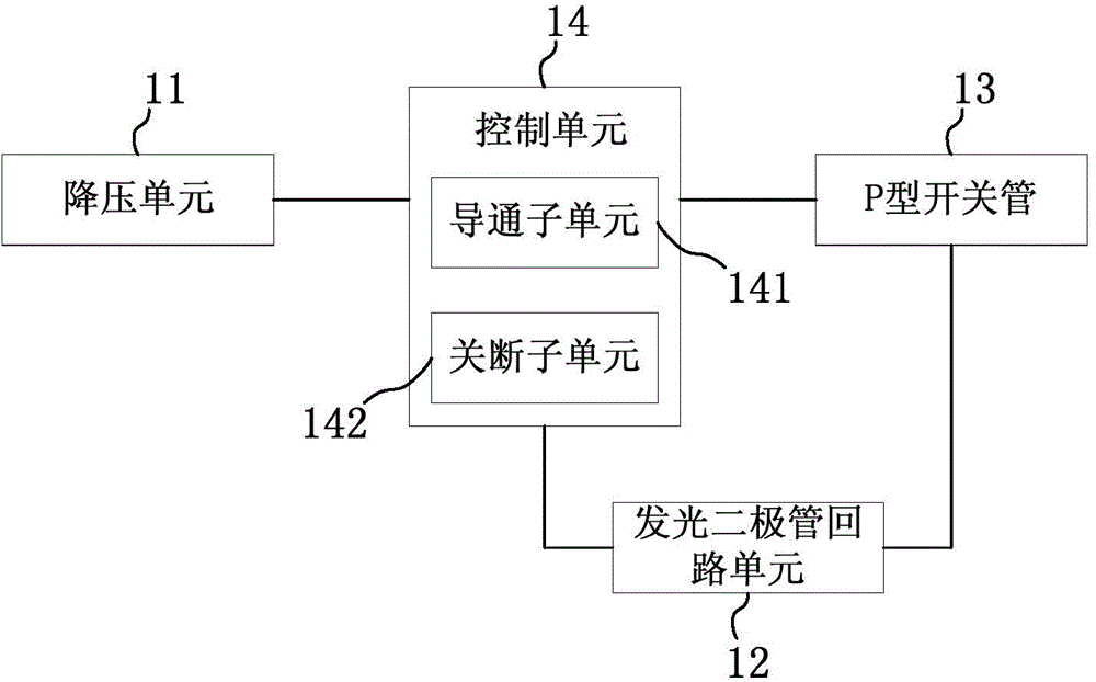
[0030] An embodiment of the present invention provides a buck type light emitting diode circuit. figure 2 It is a structural schematic diagram of a BUCK type light-emitting diode circuit provided by an embodiment of the present invention. Such as figure 2As shown, the BUCK-type light-emitting diode circuit includes: a step-down unit 11, a light-emitting diode circuit unit 12, a P-type switch tube 13 and a control unit 14, wherein the step-down unit 11 is used to input from the grid to the BUCK-type The AC voltage of the li...


PUM


Abstract

The invention discloses a BUCK-type light emitting diode circuit. The circuit comprises a voltage reduction unit, a light emitting diode loop unit, a P-type switch tube and a control unit. The voltage reduction unit is used to carry out voltage reduction on an alternating voltage which is input to the BUCK-type light emitting diode circuit from a power grid. The control unit comprises a Darlington tube formed by two P-type bipolar triodes. The control unit is connected to the voltage reduction unit and the P-type switch tube and controls shutoff of the P-type switch tube through temperature compensation and voltage feedback. The light emitting diode loop unit comprises at least one light emitting diode. The light emitting diode loop unit is connected to the P-type switch tube and the control unit and makes the light emitting diode continuously give out light under the condition that the P-type switch tube is turned off. By using the BUCK-type light emitting diode circuit, when the alternating voltage input by the power grid generates fluctuations or an environment temperature generates fluctuations, a current of the light emitting diode in the circuit is stable.

Description

technical field [0001] The invention relates to the field of electronic technology, in particular to a BUCK type light emitting diode circuit. Background technique [0002] BUCK type circuit, also known as step-down conversion circuit, this circuit can step down a higher input voltage, and then output to the load connected to the circuit to provide the load with working voltage, for example, BUCK type circuit can be used for lighting Light emission of a diode (Light-Emitting Diode, LED for short) provides an operating voltage. [0003] figure 1 It is the circuit diagram of the BUCK type LED circuit in the prior art. Such as figure 1 As shown, the BUCK type LED circuit includes: a fuse FUS, a rectifier bridge composed of four first diodes DS1, an inductor LS1, a first capacitor to a third capacitor (CS1-CS3), a first LED LDS1, the second light-emitting diode LDS2, the second diode DS2, the third diode DS3, the primary winding TS1 and the secondary winding TS2 of the trans...

Claims


Application Information

Patent Timeline
Patent Type & Authority Applications(China)
IPC IPC(8): H05B37/02
Inventor 朱方杰胡健峰吕文生
Owner WUXI CHINA RESOURCES HUAJING MICROELECTRONICS
Why Eureka
Try Eureka