
Ligament assembly

a technology of ligaments and joints, applied in the field of ligaments, can solve the problems of difficult to match the properties of artificial fibres, proved extremely difficult, and difficult to replicate the natural kinematics of joints without the presence of naturally functioning ligaments

Active Publication Date: 2018-05-29
BIOMET UK HEALTHCARE
View PDF25 Cites 3 Cited by
  • Summary
  • Abstract
  • Description
  • Claims
  • Application Information

AI Technical Summary

Benefits of technology

The present invention provides a ligament assembly that includes a resilient element connected to a bone anchor and a ligament. The resilient element helps to resist loads that are transmitted between the bone anchor and the ligament by bending and resisting them. This results in a more robust and reliable ligament assembly.

Problems solved by technology

To date, it has been impossible to match these properties using artificial fibres.
However, if surrounding bone tissue is diseased or damaged, it may be necessary to remove both the natural ligament and the adjacent one tissue and replace them with prosthetic components.
However, it has proved extremely difficult to replicate the natural kinematics of a joint without the presence of naturally functioning ligaments.

Method used


Image

  • Ligament assembly
  • Ligament assembly
  • Ligament assembly

Examples


Embodiment Construction

[0050]In this specification, the terms anterior, posterior, lateral and medial are used in relation to a ligament assembly implanted in a patient.

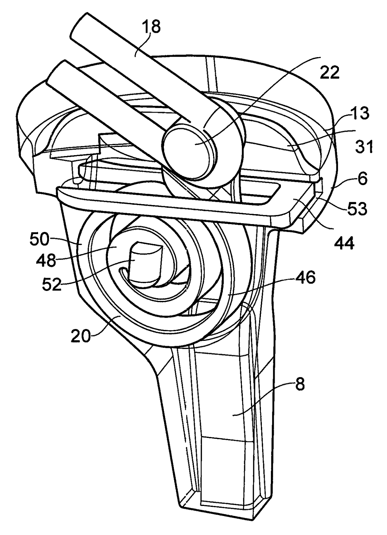
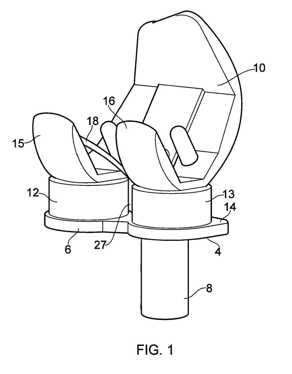
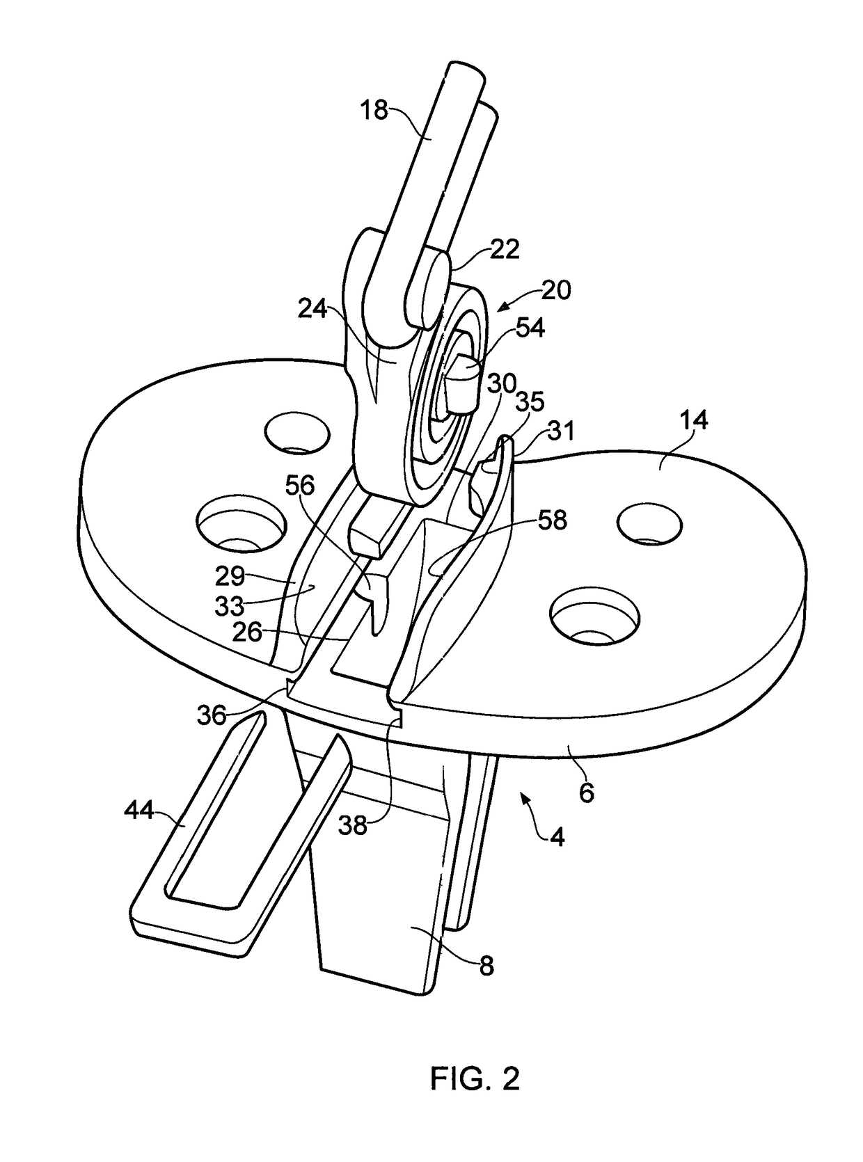
[0051]Referring to FIGS. 1 and 2, a knee prosthesis incorporating a ligament assembly 2 comprises a tibial component 4 having a tibial tray 6 integrally formed with a stem 8, a femoral component 10 and a pair of bearing components 12, 13. The bearing components 12, 13 separate the tibial component 4 and femoral component 10, and are formed with proximal and distal bearing surfaces which engage corresponding bearing surfaces 14, 15, 16 on the tibial tray 6 and on the femoral component 10. These various bearing surfaces enable the tibial component 4 to rotate and translate relative to the femoral component 10. One or both of the bearing components 12, 13 may be meniscal bearing components, rotational platform bearing components, or fixed bearing components.

[0052]An artificial ligament 18 is connected at one end to the femoral component 10, a...


PUM


Abstract

A ligament assembly (2) comprising a resilient element (20) connected to a bone anchor (4) and a ligament (18), the resilient element (20) acting m a cantilever and resisting toads transmitted between the bone anchor (4) and the ligament (18) by virtue of the resistance to bending of the resilient element. The ligament (18) may comprise an artificial ligament (18) which is adapted to replace a human or animal ligament. The resilient element (20) may comprise a spiral spring and may act as a biasing element / shock absorber operatively coupled to the artificial ligament (18) to control the effective stiffness of the artificial ligament (18). Consequently, the resilient element (20) enables an effective stiffness of the artificial ligament (18) to be achieved that more closely approximates the stiffness of a natural ligament.

Description

PRIORITY APPLICATIONS[0001]This application is a U.S. National Stage Application under 35 U.S.C. 371 from PCT Application No. PCT / GB2014 / 052350, filed Jul. 31, 2014, which claims the benefit of priority to GB application Serial No. 1314410.0, filed Aug. 12, 2013, the contents of which are hereby incorporated by reference in their entireties.[0002]This invention relates to a ligament assembly comprising a resilient element connected to a bone anchor and a ligament, the resilient element acting as a cantilever and resisting loads transmitted between the bone anchor and the ligament by virtue of the resistance to bending of the resilient element.BACKGROUND[0003]It is known to reattach a damaged ligament using a conventional bone anchor. It is also known to implant an artificial ligament to replace a natural ligament which has become damaged. Conventional artificial ligaments are formed from strands or bundles of artificial fibres which may be woven and / or aligned to form a flexible mem...

Claims


Application Information

Patent Timeline
Patent Type & Authority Patents(United States)
IPC IPC(8): A61F2/08A61F2/38A61F2/30
CPCA61F2/0811A61F2/38A61F2/3836A61F2220/0008A61F2002/30462A61F2002/30481A61F2002/30573A61F2002/0852A61F2/08A61F2002/0835
Inventor DODD, CHRISTOPHERMURRAYO'CONNOR, JOHNLLOYD, RUSSELLALINEJAD, MONA
Owner BIOMET UK HEALTHCARE
Learn More