
Steering control device

a control device and steering angle technology, applied in the direction of electric steering, power driven steering, vehicle components, etc., can solve the problems of steering angle exceeding the upper limi

Active Publication Date: 2018-05-29
JTEKT CORP
View PDF10 Cites 0 Cited by
  • Summary
  • Abstract
  • Description
  • Claims
  • Application Information

AI Technical Summary

Benefits of technology

The solution effectively restrains the steering from exceeding its upper limit values, reducing the risk of operational errors and maintaining the reliability of the steering system by performing limiting control before reaching the physical limits, thus preventing excessive steering angle or steered angle changes.

Problems solved by technology

This can restrain the steering from being operated to cause the steered angle to exceed its upper limit value and can also restrain the steering from being operated to cause the steering angle to exceed its upper limit value

Method used


Image

  • Steering control device
  • Steering control device
  • Steering control device

Examples


Embodiment Construction

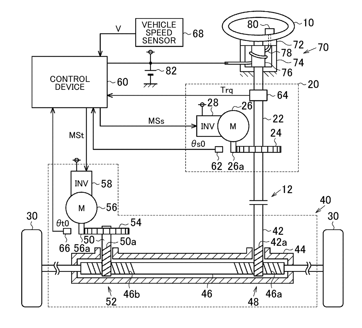
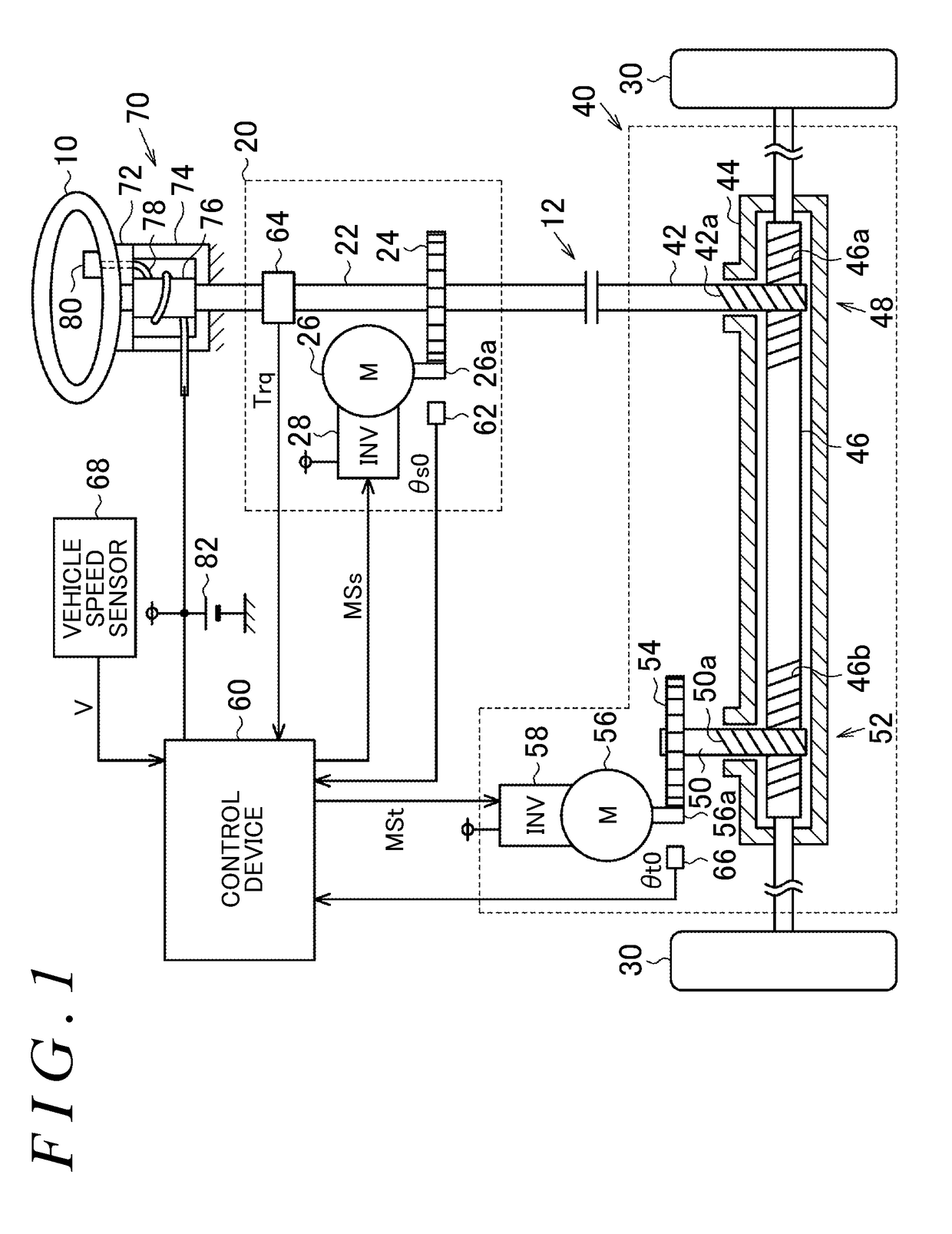
[0020]A first embodiment of a steering control device of the present invention will be described below with reference to the accompanying drawings. As shown in FIG. 1, in a steering device of the present embodiment, a steering wheel 10 that receives input for a steering (steering mechanism) is connected to a reaction force actuator 20 that applies a reaction force, or a force against operation of the steering wheel 10. The reaction force actuator 20 includes a steering shaft 22 fixed to the steering wheel 10, a reaction force-side reduction gear 24, a reaction force motor 26 having a rotary shaft 26a coupled to the reaction force-side reduction gear 24, and an inverter 28 that drives the reaction force motor 26.

[0021]The steering shaft 22 can be coupled to a pinion shaft 42 of a steering actuator 40 via a clutch 12. The steering actuator 40 includes a first rack and pinion mechanism 48, a second rack and pinion mechanism 52, a steered-side motor 56, and an inverter 58.

[0022]The firs...


PUM


Abstract

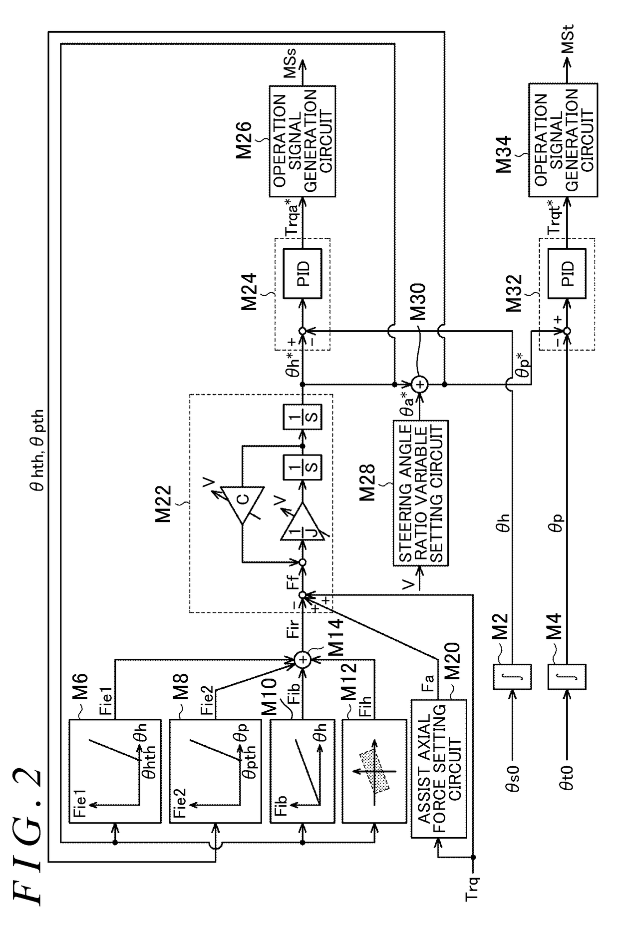
A steering control device can restrain a steering from being operated to cause a steered angle and a steering angle to exceed their upper limit values. A first limiting reaction force setting circuit increases a first reaction force rapidly if the steering angle becomes no smaller than a steering angle threshold. A second limiting reaction force setting circuit increases a second reaction force rapidly if the steered angle becomes no smaller than a steered angle threshold. A target steering angle setting circuit sets a target steering angle based on steering torque applied to the steering minus the first reaction force, the second reaction force, etc. A steering angle control circuit sets reaction torque as a manipulated variable for feedback controlling the steering angle to the target steering angle. An operation signal generation circuit outputs an operation signal to a reaction force motor so as to achieve reaction torque.

Description

INCORPORATION BY REFERENCE[0001]The disclosure of Japanese Patent Application No. 2015-146896 filed on Jul. 24, 2015 including the specification, drawings, and abstract, is incorporated herein by reference in its entirety.BACKGROUND OF THE INVENTION[0002]1. Field of the Invention[0003]The present invention relates to steering control devices that output an operation signal to a steering device that can change the steering angle ratio, namely the ratio between the steered angle of steered wheels of a vehicle and the steering angle, or the rotation angle of a steering.[0004]2. Description of the Related Art[0005]Conventionally, in steering devices, there is an upper limit value permitted for the steered angle of the steered wheels. For example, in those steering devices having a rack and pinion mechanism, axial displacement of a rack is restricted by a rack stopper (end stopper). There is also an upper limit value for the steering angle of the steering wheel in accordance with the upp...

Claims


Application Information

Patent Timeline
Patent Type & Authority Patents(United States)
IPC IPC(8): B62D6/08B62D6/00B62D5/00
CPCB62D5/008B62D6/008B62D5/04B62D5/046B62D6/00B62D5/0469
Inventor KODERA, TAKASHI
Owner JTEKT CORP
Learn More