Method and apparatus for blinding non-energy sources

a non-energy source and blinding technology, applied in the direction of mechanical equipment, flanged joints, pipe elements, etc., can solve the problem that the hose cannot be attached to the bleeder guard, and achieve the effect of quick and efficient blinding a non-energy sour

Active Publication Date: 2018-05-29
MARATHON PETROLEUM
View PDF15 Cites 0 Cited by
  • Summary
  • Abstract
  • Description
  • Claims
  • Application Information

AI Technical Summary

Benefits of technology

[0006]An apparatus has been developed for quickly and efficiently blinding a non-energy source. A bleeder guard is attached to a non-energy source. The bleeder guard prevents another operator from attaching anything to the non-energy source. This bleeder guard is generally cylindrical, having one end threaded while

Problems solved by technology

The unthreaded end of the bleeder guard, being exposed, renders it un-attachable to an energy source and therefore, protects the operator inside the vessel from exposure to energy sou

Method used


Image

  • Method and apparatus for blinding non-energy sources
  • Method and apparatus for blinding non-energy sources
  • Method and apparatus for blinding non-energy sources

Examples


Embodiment Construction

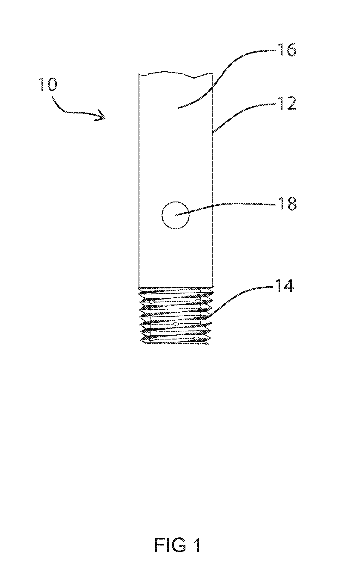
[0015]FIG. 1 is a view of the bleeder guard 10 of this invention. Bleeder guard 10 is an elongated rod 12. Elongated rod 12 has a first end having a threaded surface 14 and a second end having a smooth surface 16. FIG. 1 also shows a hole 18 through smooth surface 16 of bleeder guard 10.

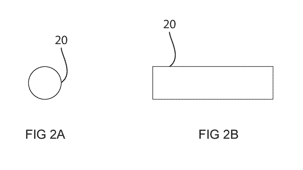
[0016]FIGS. 2A and 2B are an end view and a side view of lock 20 according to this invention. Lock 20 is placed through hole 18 of bleeder guard 10.

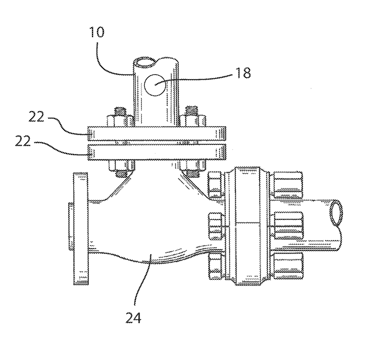
[0017]FIG. 3 is a view showing bleeder guard 10 of this invention attached to flanged joint 22. Flanged joint 22 has an aperture (not shown) passing therethrough. The aperture has a threaded surface (not shown). Threaded surface 14 of bleeder guard 10 engages the threaded surface of the aperture. Threaded surface 14 and the threaded surface of flange 22 co-operate to reduce leaks and blind a vessel 24 attached to flange 22.

[0018]FIGS. 4A and 4B are a top view and side view showing prior art blind 30. The blind 30 used is a flat pancake shaped device. The ...


PUM


Abstract

This bleeder guard is used for blinding pipe flanges in refineries, chemical plants, and other fluid processing plants joined in many places by flanged joints. The bleeder guard is an elongated rod, having a first end with a threaded surface and a second end with a smooth surface. The bleeder guard preferably is a smooth elongated rod of uniform diameter. The elongated rod typically has a cylindrical shape.

Description

CROSS-REFERENCE TO RELATED APPLICATION[0001]The present patent application is based upon and claims the benefit of provisional patent application No. 62 / 095,917, filed on Dec. 23, 2014.FIELD OF THE INVENTION[0002]This invention relates to an improved way of blinding pipe flanges in refineries, chemical plants, and other fluid processing plants joined in many places by flanged joints.BACKGROUND OF THE INVENTION[0003]In a refinery, tank farm or other industrial setting where personnel must enter a vessel to inspect, repair or maintain the vessel any energy source or inlet capable of allowing energy to enter into the vessel is blinded. To prevent dangerous energy or other substances from entering the vessel a blind, usually a flat pancake like piece is inserted between a set of flanges that have been loosened. This blind blocks any flow through the pipe and allows personnel to enter a vessel without risk of harm.[0004]Blinding does increase a risk of leakage and is extremely time consu...

Claims


Application Information

Patent Timeline
IPC IPC(8): F16L55/10F16K3/312
CPCF16K3/312F16L55/10F16L23/003
Inventor MARON, MICHAEL
Owner MARATHON PETROLEUM
Why Eureka
Try Eureka