LED lamp filament

a technology of led lamp filament and filament, which is applied in the direction of lighting and heating apparatus, semiconductor devices for light sources, and support devices for lighting and heating. it can solve the problem of not achieving luminescence effect, and achieve the effect of increasing the emitting angle of led lamp filamen

Active Publication Date: 2018-05-29
TCL VERY LIGHTING TECH HUIZHOU CO LTD +1
View PDF8 Cites 46 Cited by
  • Summary
  • Abstract
  • Description
  • Claims
  • Application Information

AI Technical Summary

Benefits of technology

[0015]In the LED lamp filament mentioned above, the configuration of the protrusions causes the light source emitted from light emitting units to emit towards a side of the substrate which is opposite to the side covered by the fluorescent adhesive layer, thereby increasing an emitting angle of the LED lamp filament.

Problems solved by technology

The LED lamp filament packaged by the LED holder has a small emitting angle, and cannot achieve a luminescence effect equivalent to that of an incandescent lamp filament having.

Method used


Image

  • LED lamp filament
  • LED lamp filament
  • LED lamp filament

Examples


Embodiment Construction

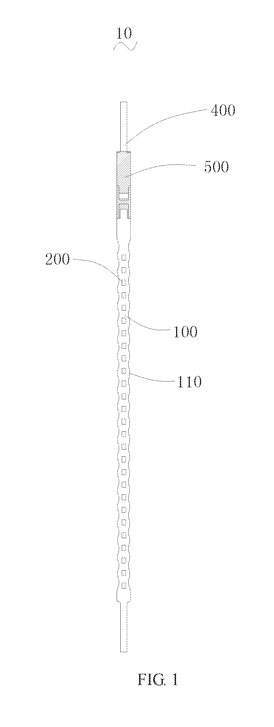
[0018]FIG. 1 is a frontal view of a LED lamp filament 10 according to one embodiment.

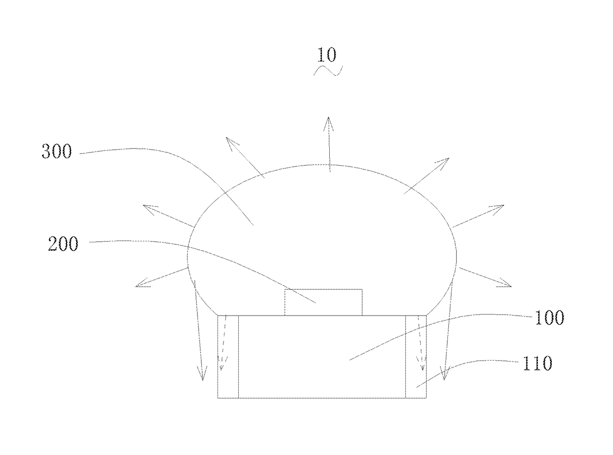
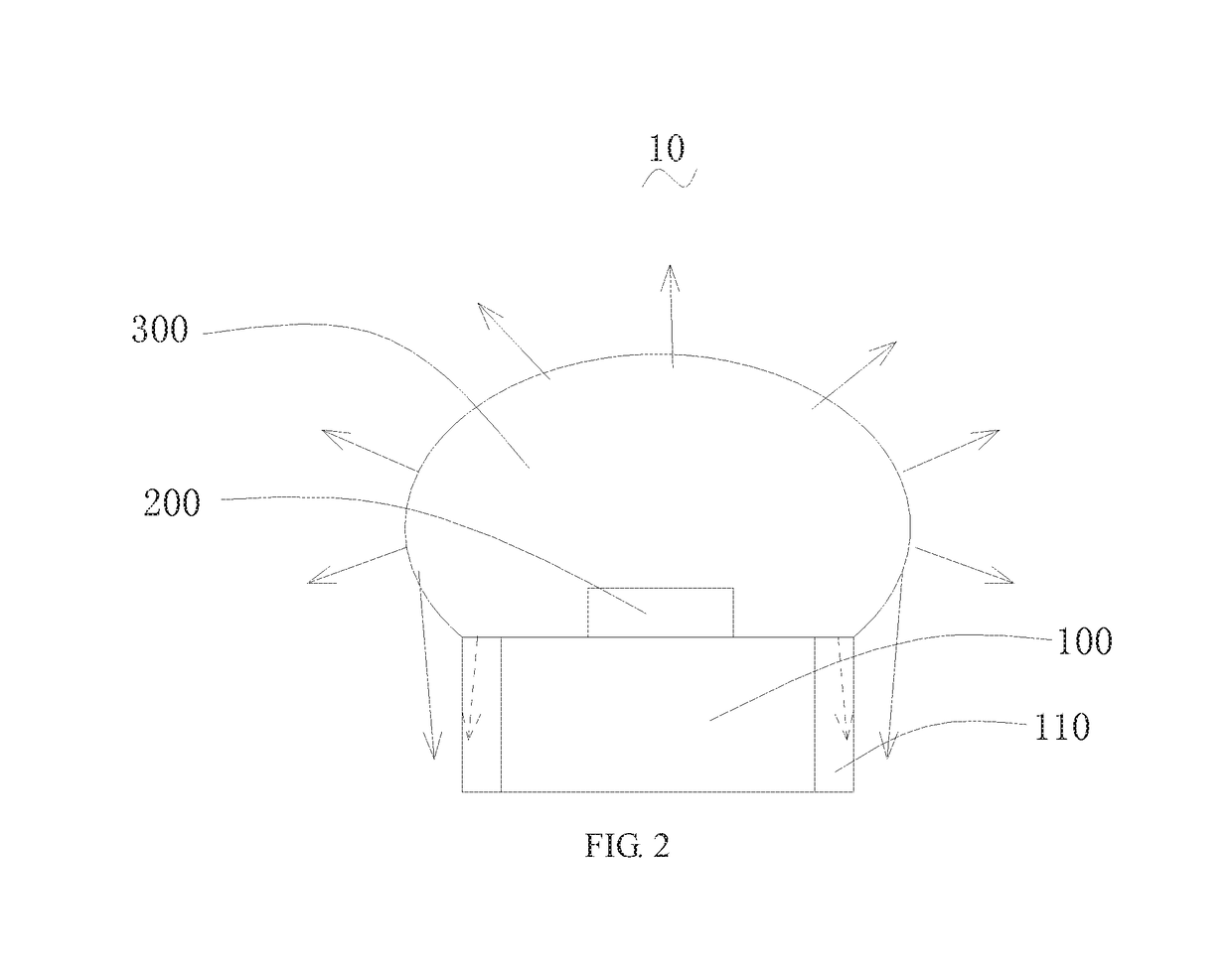
[0019]The LED lamp filament 10 includes: an elongated substrate 100, a plurality of light emitting units 200 located on a first surface of the substrate 100 and distributed along an extending direction of the substrate 100, and a fluorescent adhesive layer 300 covering the first surface and the plurality of light emitting units 200 (see FIG. 2), a pin 400 and an insulating connector 500 connected to the pin 400 and the substrate 100. At least one side of the substrate 100 is provided with a plurality of protrusions 110, and the protrusions 110 are distributed along the extending direction of the substrate 100. The fluorescent adhesive layer 300 further covers the protrusions 110 and a region between adjacent two protrusions 110.

[0020]Opposite sides of the substrate are provided with a plurality of protrusions 110, respectively. The plurality of protrusions 110 are symmetrically arranged, a minimum w...


PUM


Abstract

A LED lamp filament, comprising: a long strip-shaped substrate, a plurality of light-emitting units arranged on a first surface of the substrate and distributed along the extending direction of the substrate, and a light-transmittable fluorescent glue layer covering the first surface and the plurality of light-emitting units. A plurality of bulges are provided on at least one side of the substrate, and the bulges are distributed along the extending direction of the substrate; one part of light excited by the fluorescent glue layer and emitted from the light-emitting units emits out in a direction towards a second surface, opposite to the first surface, of the substrate from a space between adjacent bulges.

Description

FIELD OF THE INVENTION[0001]The present disclosure relates a technical field of LED, and more particularly, relates to a LED lamp filament.BACKGROUND OF THE INVENTION[0002]LED serves as a new light source and is extensively applied to various lightings due to its advantages of a better energy saving effect and a longer service life. The white LED is praised as the fourth generation lighting source which replaces the fluorescent lamp and the incandescent lamp. The LED modifies luminescence principles of the incandescent lamp which luminescence by tungsten filament and the fluorescent lamp which luminescence by three-basis-color powder, it takes advantages of an electric field to luminescence, and processes advantages of a high lighting efficient, non radiation, a long service life, a low power consumption, and environment protection.[0003]The conventional LED holder generally has a cup or bowl shape with a small volume. The LED lamp filament packaged by the LED holder has a small emi...

Claims


Application Information

Patent Timeline
Patent Type & Authority Patents(United States)
IPC IPC(8): F21V21/00H01L33/52F21V19/00H01L25/075F21S4/20H01L33/50F21K9/235H01L33/64F21K9/232F21Y103/10F21Y115/10
CPCF21S4/20F21K9/235F21V19/001H01L25/075H01L25/0753H01L33/505H01L33/52H01L33/642H01L2924/0002F21K9/232F21Y2103/10F21Y2115/10H01L2924/00H01L33/64
Inventor MA, WENBOLIAO, QIURONG
Owner TCL VERY LIGHTING TECH HUIZHOU CO LTD
Why Eureka
Try Eureka