
Furnace cabinet with nozzle baffles

Active Publication Date: 2018-05-29
TRANE INT INC
View PDF9 Cites 2 Cited by
  • Summary
  • Abstract
  • Description
  • Claims
  • Application Information

AI Technical Summary

Benefits of technology

The patent text describes a furnace design that includes a furnace cabinet, a primary heat exchanger, a secondary heat exchanger, and two baffles. The baffles are located within the furnace cabinet and work together to create a nozzle that helps to improve heat exchange between the airflow and the primary heat exchanger. The furnace is also designed to have an improved circulation airflow path that increases the efficiency of the heat exchangers. Additionally, the furnace can be used with a fan to further enhance the air flow and improve heat exchange. The technical effect of the furnace design is to optimize heat exchange and improve overall efficiency of the furnace.

Problems solved by technology

In some furnaces, there may be a trade-off between reducing the tube temperatures, increasing air velocities, and increasing pressure drop, and thus increasing power consumption of a circulation fan blower motor.
As tube temperatures decrease, external air velocities may increase, pressure drops may increase, power consumption may increase, and furnace fan efficiency may decrease.

Method used


Image

  • Furnace cabinet with nozzle baffles
  • Furnace cabinet with nozzle baffles
  • Furnace cabinet with nozzle baffles

Examples


Embodiment Construction

[0026]Some furnaces may have airflow paths that are not optimized for contacting a heat exchanger with the airflow through the airflow paths. Allowing air to pass through a furnace while producing unnecessary recirculation patterns and separation zones adjacent to a heat exchanger may reduce the efficiency of the furnace. In some embodiments of this disclosure, a condensing gas-fired furnace is provided that efficiently manages airflow through the furnace, increases airflow contact with a heat exchanger installed in the furnace, and consequently increases the efficiency of the furnace.

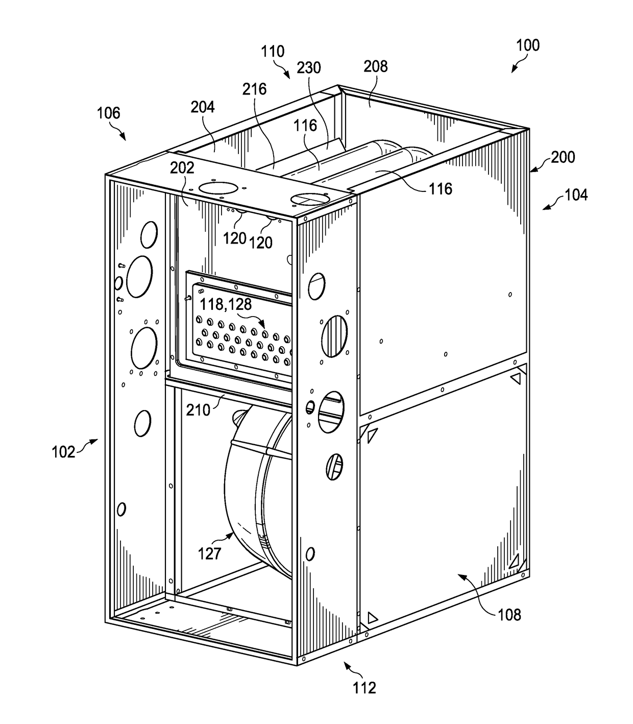
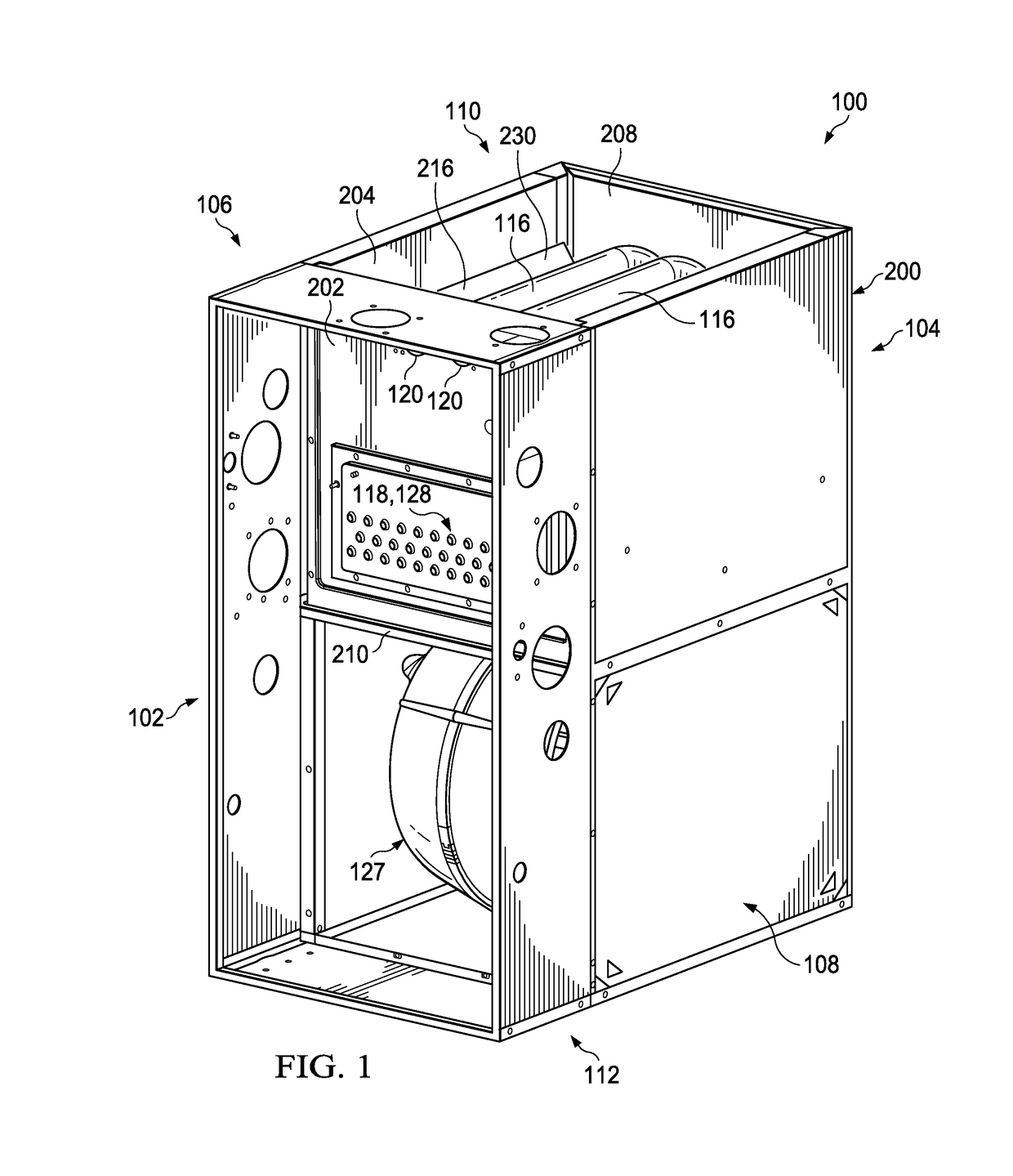
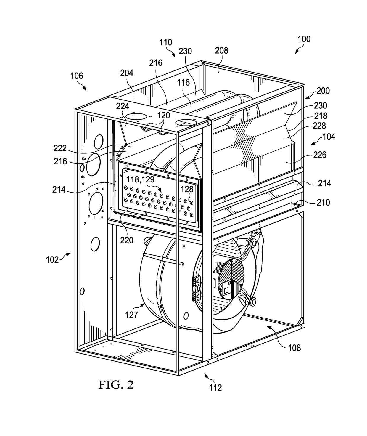
[0027]Referring now to FIGS. 1 and 2, an oblique right side view of a condensing gas-fired furnace 100 and another oblique right side view of the furnace 100 having some right side components of the furnace 100 removed to better show the interior components of the furnace 100 are shown, respectively, according to an embodiment of the disclosure. In this embodiment, the furnace 100 is configured as an i...


PUM


Abstract

A condensing gas-fired furnace has a furnace cabinet, a primary heat exchanger, a secondary heat exchanger located upstream relative to the primary heat exchanger with regard to location within a circulation airflow path, a first baffle carried by a first wall of the furnace cabinet, and a second baffle carried by a second wall of the furnace cabinet, wherein the second baffle is located opposite the first baffle, and wherein the second wall is located opposite the first wall. The first baffle and the second baffle cooperate to form a nozzle within the furnace cabinet. A third baffle and a fourth baffle extend from the bottom of the first baffle and the second baffle, respectively, to the blower deck located adjacent to a secondary heat exchanger.

Description

CROSS-REFERENCE TO RELATED APPLICATIONS[0001]The present application claims priority under 35 U.S.C. 119(e) to U.S. Provisional Patent Application No. 62 / 076,974 filed on Nov. 7, 2014 by Wagers, et al., and entitled “Furnace Cabinet with Nozzle Baffles,” the disclosure of which is hereby incorporated by reference in its entirety.STATEMENT REGARDING FEDERALLY SPONSORED RESEARCH OR DEVELOPMENT[0002]Not applicable.REFERENCE TO A MICROFICHE APPENDIX[0003]Not applicable.BACKGROUND[0004]Some heating, ventilation, and / or air conditioning (HVAC) systems often comprise a furnace for heating and / or otherwise conditioning interior spaces. Some HVAC systems comprise furnaces with baffles configured to redirect airflow into contact with heat exchangers. In some cases, baffles are placed in a heat exchanger compartment to reduce primary tube temperatures and increase the life expectancy of such tubes. In some furnaces, there may be a trade-off between reducing the tube temperatures, increasing ai...

Claims


Application Information

Patent Timeline
IPC IPC(8): F24H3/08F24H9/00
CPCF24H3/087F24H9/0068F24H8/00Y02B30/00
Inventor WAGERS, NATHANTOTARO, ROSARIOSUN, BRIGHT WEI LIANGZHAO, SHUO
Owner TRANE INT INC
Learn More