
Humidifier for respiratory apparatus

a technology for respiratory apparatus and humidifier, which is applied in the direction of lighting and heating apparatus, diagnostic recording/measuring, combustion types, etc., can solve the problems of poor heat transfer, poor heat transfer, poor heat transfer method of patient conduit,

Active Publication Date: 2008-05-08
RESMED LTD
View PDF41 Cites 367 Cited by
  • Summary
  • Abstract
  • Description
  • Claims
  • Application Information

AI Technical Summary

Benefits of technology

[0018]A further sample embodiment of the invention provides a method of increasing patient comfort during start-up of humidification, the method comprising providing a heating element to thermally contact breathable gas being provided to the patient along a gas flow path and to thermally contact water in a humidifier apparatus; and configuring the heating element to heat the gas in the gas flow path and to heat the water in the humidifier apparatus, such the patient is initially provided with heated gas while the temperature of the water in the humidifier apparatus is being increased to its operating temperature.

Problems solved by technology

Such a heating method for the patient conduit may only provide poor heat transfer due to the wire locating itself along the conduit wall rather than in the main gas stream.
A wire will also only give poor turbulent mixing due to its low profile.
As a result heat transfer may be poor and the mixing of water vapor and gas may also be poor.
None of these prior art devices provides an entirely satisfactory solution to the provision of comfortable humidified breathable gas to the patient, nor to ease of construction and hygiene requirements and to energy and patient comfort requirements at startup.

Method used


Image

  • Humidifier for respiratory apparatus
  • Humidifier for respiratory apparatus
  • Humidifier for respiratory apparatus

Examples


Embodiment Construction

[0074]Flexible Tape Heater

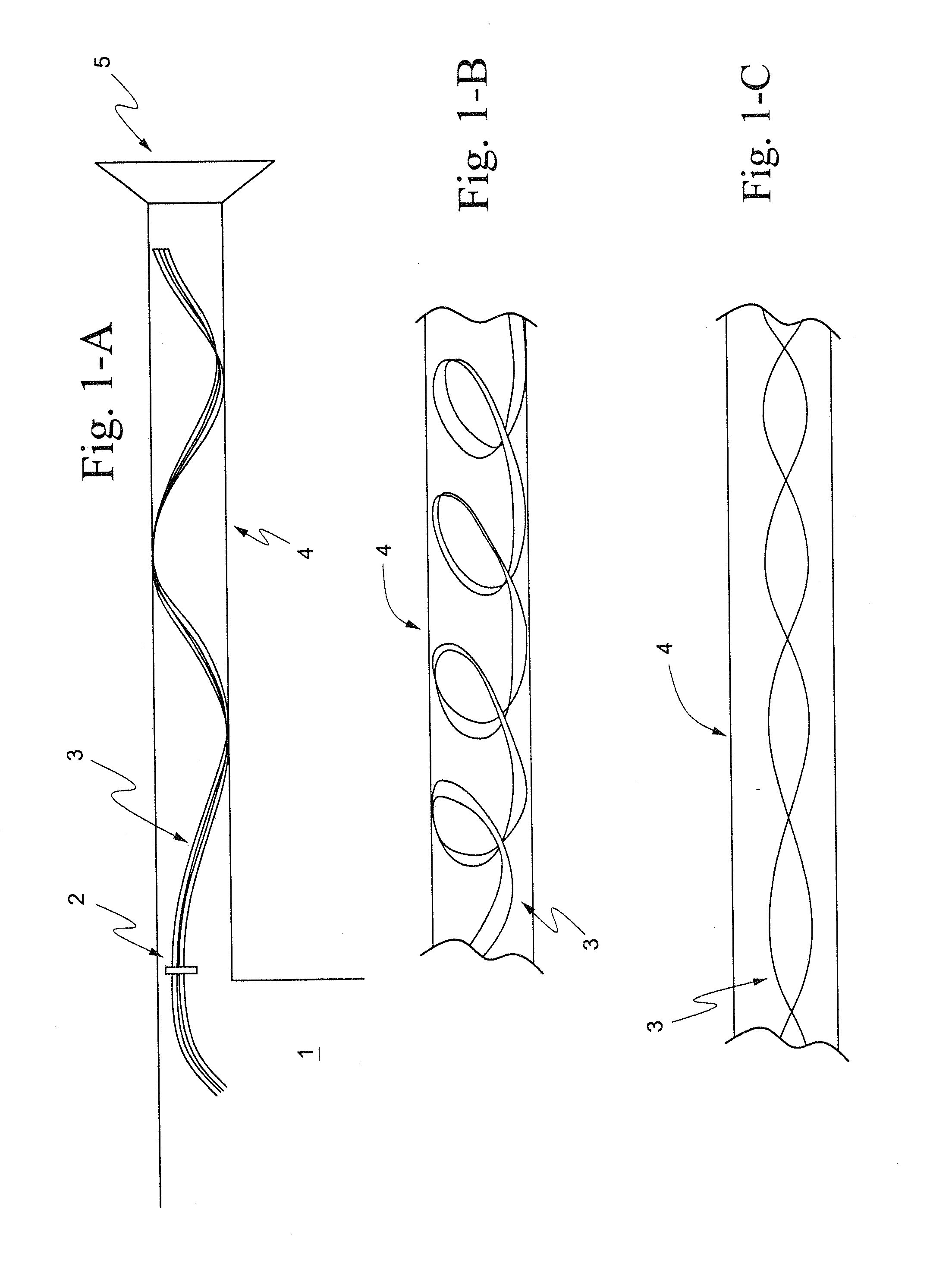
[0075]FIGS. 1-A to 1-C illustrate the use of a flexible tape heater 3 within the patient conduit 4 of a respiratory apparatus. The patient conduit 4 is located between the humidification chamber 1 and the patient interface, e.g. mask 5. The patient conduit 4 conveys the flow of gas from the humidification chamber 1 to the patient mask 5 in respiratory apparatus. The humidification chamber 1 in turn receives pressurized gas from a flow generator 20 (FIG. 5) or blower.

[0076]The flexible tape heater 3 in the patient conduit 4 is used to heat the flow of gas in the patient conduit 4. Heating of the gas enables the gas comfort features of temperature and humidity to be attained and maintained for the gas delivered by the respiratory apparatus.

[0077]The flexible tape heater 3 is electrically coupled to a heater controller 21 (FIG. 5) by a patient conduit connector end 2. The heater controller 21 may be incorporated in the humidifier or the flow generator 20 or th...


PUM


Abstract

A respiratory apparatus for delivering breathable gas to a patient includes a flow generator that generates a supply of pressurised gas to be delivered to the patient; a humidifier for vaporising water and delivering water vapor to humidify the gas; a gas flow path leading from the flow generator to the humidifier and from the humidifier to a patient interface; and a heater in thermal contact with the gas and / or the water, wherein the heater comprises an elongate heating filament in the form of a tape. A humidifier for respiratory apparatus includes a first respiratory gas passage for receiving gas from a flow generator, a humidifier chamber, a second respiratory gas passage for delivering humidified gas to a patient interface, and a heater in thermal contact with the gas and / or the water, wherein the heater comprises an elongate heating filament extending along at least part of both said first and second respiratory gas passages. A conduit for use in a respiratory apparatus for delivering breathable gas to a patient includes a tube; a helical rib on an outer surface of the tube; and a plurality of wires supported by the helical rib in contact with the outer surface of the tube.

Description

CROSS REFERENCE TO RELATED APPLICATIONS[0001]This application claims priority to U.S. Application 60 / 955,222, filed Aug. 10, 2007, and to Australian Provisional Application 2006906224, filed Nov. 8, 2006, the entire contents of both of which are incorporated herein by reference.BACKGROUND OF THE INVENTION[0002]1. Field of the Invention[0003]The present invention relates to humidification and heater arrangements used to control the humidity of breathable gases used in all forms of respiratory apparatus ventilation systems including invasive and non-invasive ventilation, Continuous Positive Airway Pressure (CPAP), Bi-Level therapy and treatment for sleep disordered breathing (SDB) conditions such as Obstructive Sleep Apnea (OSA), and for various other respiratory disorders and diseases.[0004]2. Description of Related Art[0005]Respiratory apparatus commonly have the ability to alter the humidity of the breathable gas in order to reduce drying of the patient's airway and consequent pati...

Claims


Application Information

Patent Timeline
IPC IPC(8): A61M16/00F16L11/04
CPCA61M16/0066A61M16/161A61M16/0816A61M16/0875A61M16/1075A61M16/16A61M2016/0027A61M2016/0039A61M2205/14A61M2205/3368A61M2205/3375A61M2205/3569A61M2205/3584A61M2205/3592A61M2205/3633A61M2205/3653A61M2205/6018A61M2205/6054A61M2230/04A61M16/108A61M16/1085A61M16/109A61M16/1095A61M16/06A61M16/0633A61M16/0825A61M16/0003A61M16/0057A61M2205/3334
Inventor KLASEK, PAUL JANVIRR, ALEXANDERROW, NATHAN JOHNHUBY, RONALD JAMESCHENG, JACK WEI
Owner RESMED LTD
Learn More