Linear displacement measuring apparatus

a measuring apparatus and linear displacement technology, applied in the direction of measuring devices, electrical/magnetically converting sensor outputs, instruments, etc., can solve problems such as inability to obtain correct results

Active Publication Date: 2018-06-05
MITUTOYO CORP
View PDF10 Cites 0 Cited by
  • Summary
  • Abstract
  • Description
  • Claims
  • Application Information

AI Technical Summary

Benefits of technology

[0015]A purpose of the present invention is to provide a linear displacement measuring apparatus which notifies a user when being installed defectively.

Problems solved by technology

However, when the object (for example, the moving stage 90, the machine tool, or the like) is controlled based on the measurement value, the results cannot be correctly obtained.
Alternatively, if the linear displacement measuring apparatus 100 is mounted beyond the prescribed installation tolerance, the components constituting the linear displacement measuring apparatus 100 rub or bump together, and which can cause a breakdown.
However, the user can cause defectives due to machining errors or a breakdown without noticing this problem.

Method used


Image

  • Linear displacement measuring apparatus
  • Linear displacement measuring apparatus
  • Linear displacement measuring apparatus

Examples


first exemplary embodiment

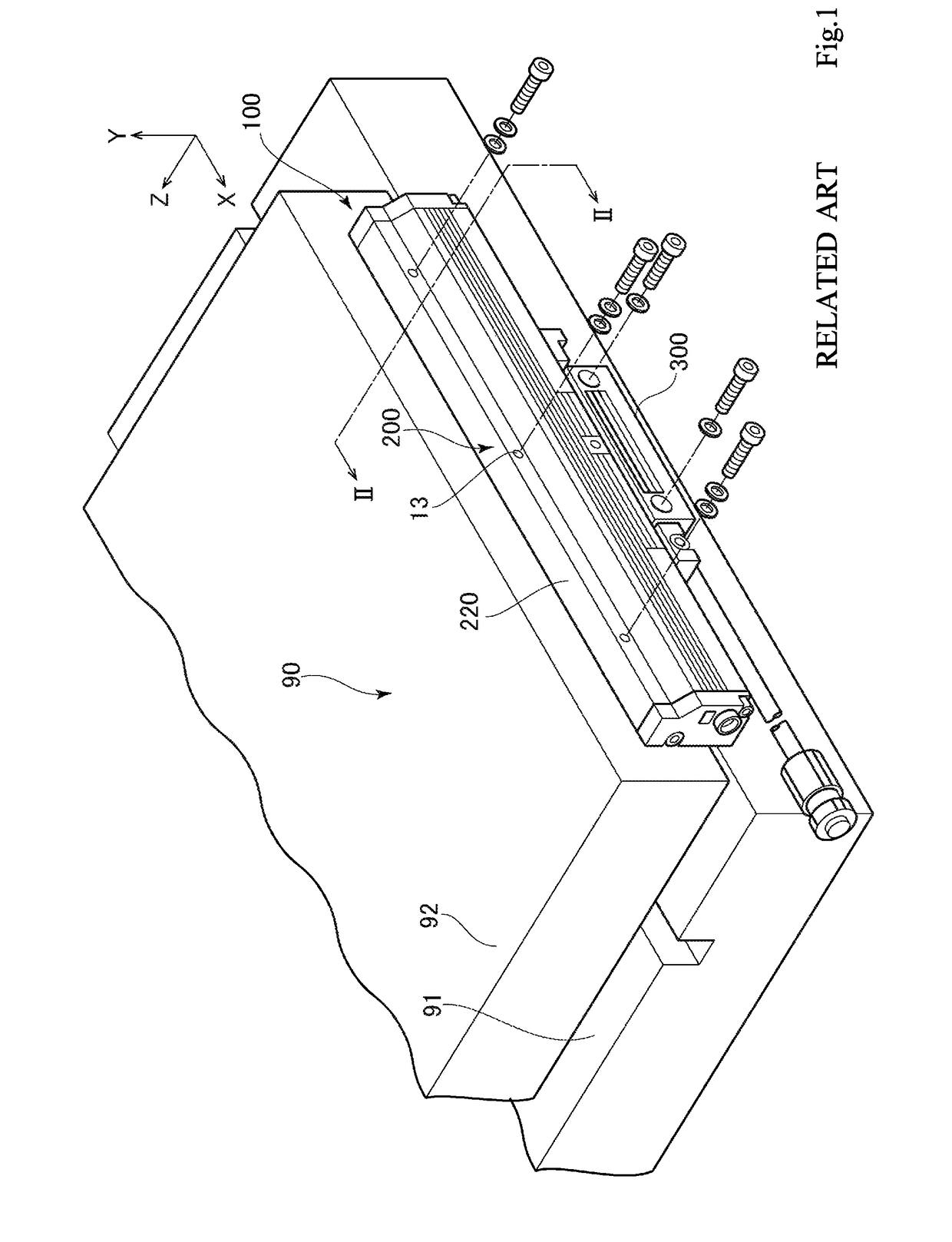
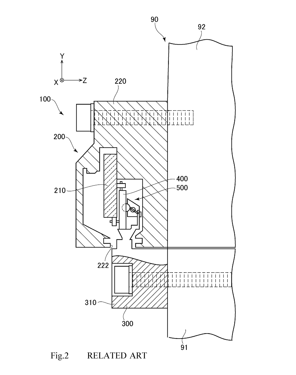
[0052]A feature of the present exemplary embodiment is mainly a structure of a slider 300, and the description of a scale part 200 is omitted since the scale part 200 is similar to the related art.

[0053]FIGS. 3 and 4 are perspective views of the slider 300.

[0054]FIG. 5 is a rear face side view of the slider 300.

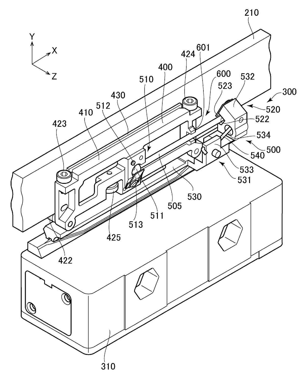
[0055]The slider 300 includes a traveling body 400, a carriage part 310, coupling means 500, and misalignment detecting means 600. The traveling body 400 travels along a main scale 210 on the main scale 210. The carriage part 310 is provided outside a scale housing case 220 and slides along the scale part 200. The coupling means 500 couples the traveling body 400 with the carriage part 310. The misalignment detecting means 600 detects an installation shift which exceeds a prescribed amount.

[0056]FIG. 6 is a perspective view of a part of the traveling body 400 and the coupling means 500 after the carriage part 310 is removed from the slider 300.

[0057]The traveling body 400 inc...

second exemplary embodiment

[0089]Next, a second exemplary embodiment of the present invention is described below.

[0090]The basic structure of the second exemplary embodiment is similar to that of the first exemplary embodiment, but a feature of the second exemplary embodiment is to add a pressing plate 603 as misalignment detecting means 600 (see FIG. 11). In the above described first exemplary embodiment, the connecting rod 505 is received between the two projecting pieces 601 separated from each other in the Y-axis direction. Thus, when the main scale 210 is inclined in the Y-axis direction, the inclination is able to be detected. However, when the main scale 210 is shifted in, for example, the Z-axis direction, the shift cannot be detected in the first exemplary embodiment.

[0091]For example, in FIG. 10, an encoder (a linear displacement measuring apparatus 100) detects the position of a gate type slider 93 which moves forward and backward in the X-axis direction.

[0092]At this time, although a scale part 20...

third exemplary embodiment

[0098]In a second exemplary embodiment, the pressing plate 603 is fixed on the base frame part 410. As means for regulating relative displacement between a connecting rod 505 and a traveling body 400 in the Z direction, for example, a pressing plate 604 may be provided at the tip of a projecting piece 601 as illustrated in FIG. 12. The pressing plate 604 is provided so as to be bent from the tip of the projecting piece 601 to have an L shape overhanging the connecting rod 505. With the pressing plate 604, an effect similar to the second exemplary embodiment is obtained.


PUM


Abstract

There is provided a linear displacement measuring apparatus which notifies a user when being installed defectively. A slider includes a traveling body which travels along a main scale on the main scale, a carriage part mounted on an object, and coupling means which couples the traveling body with the carriage part. The coupling means allows relative displacement between the traveling body and the carriage part and biases the traveling body towards the main scale. The coupling means has a connecting rod arranged so as to couple the traveling body with the carriage part via a ball joint. The slider further has misalignment detecting means which detects that the relative displacement between the traveling body and the carriage part exceeds a prescribed allowable range. The misalignment detecting means is a pair of projecting pieces arranged in a vicinity of the connecting rod so that the displacement of the connecting rod is regulated within a predetermined range.

Description

INCORPORATION BY REFERENCE[0001]This application is based upon and claims the benefit of priority from Japanese patent application No. 2015-193963, filed on Sep. 30, 2015, the disclosure of which are incorporated herein in its entirety by reference.BACKGROUND OF THE INVENTION[0002]1. Field of the Invention The present invention relates to a linear displacement measuring apparatus.[0003]2. Description of Related Art[0004]There have been used displacement measuring apparatuses, that is, what is called encoders in order for various industrial machines to accurately perform position control (for example, JP 2004-301541 A).[0005]A linear displacement measuring apparatus 100 is illustrated in FIG. 1. The linear displacement measuring apparatus 100 includes an elongate scale part 200 and a slider 300 provided so as to be slidable relatively to the scale part 200.[0006]The linear displacement measuring apparatus 100 is mounted to, for example, a moving stage 90. It is assumed that the movin...

Claims


Application Information

Patent Timeline
Patent Type & Authority Patents(United States)
IPC IPC(8): G01D5/347G01D5/244G01B3/00G01B3/08
CPCG01B3/08G01D5/34753G01D5/24442G01B3/002G01B11/02G01D5/347
Inventor KIKUCHI, KAZUSHI
Owner MITUTOYO CORP
Why Eureka
Try Eureka