Touch-sensitive linear adjustment switch

a linear adjustment and linear adjustment technology, applied in the direction of coding, pulse technique, keyboard-like device coding, etc., can solve the problems of affecting the ability of the switch to adjust and control a power source, malfunction, damage, etc., to prevent the accumulation or accumulation of dust or grime, hinder the normal operation, and compromise the convenience of use

Inactive Publication Date: 2014-04-24
CHU CHING HSIUNG
View PDF1 Cites 0 Cited by
  • Summary
  • Abstract
  • Description
  • Claims
  • Application Information

AI Technical Summary

Benefits of technology

The present invention provides a touch control switch that can adjust the power supplied to an external circuit through a simple touch along a linear direction. The switch is designed to overcome the problem of conventional mechanical switches getting loose, malfunctioning, or getting damaged after long-term use. The invention also prevents the deposition or buildup of dust or grime that may hinder the normal operation of the switch. The switch is much more practical, easy to use, and has a longer service life than mechanical switches.

Problems solved by technology

However, the mechanical components the conventional mechanical adjustment switch described above tend to get loose, malfunction, or become damaged after long-term and frequent use, not to mention that a deposition of dust or a buildup of grime on the mechanical components may, if not shortening the service life of the switch, compromise the ability of the switch to adjust and control a power source.

Method used


Image

  • Touch-sensitive linear adjustment switch
  • Touch-sensitive linear adjustment switch
  • Touch-sensitive linear adjustment switch

Examples


Embodiment Construction

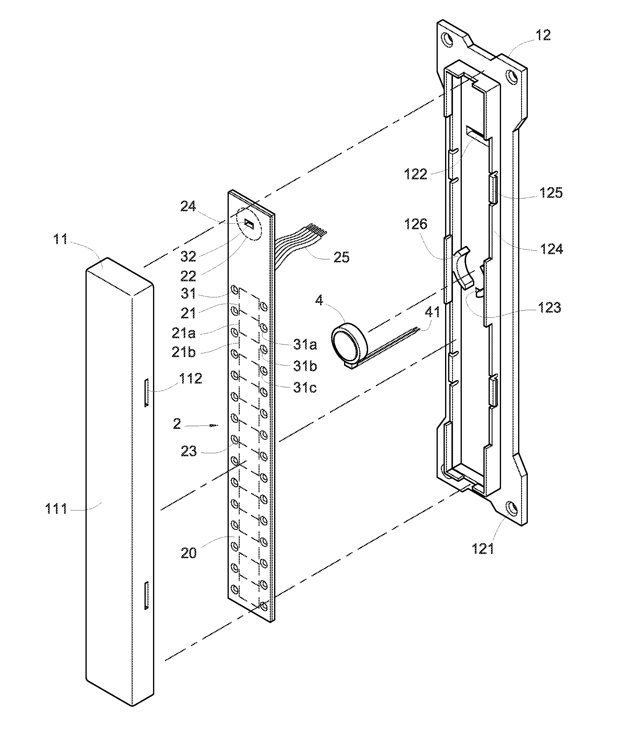
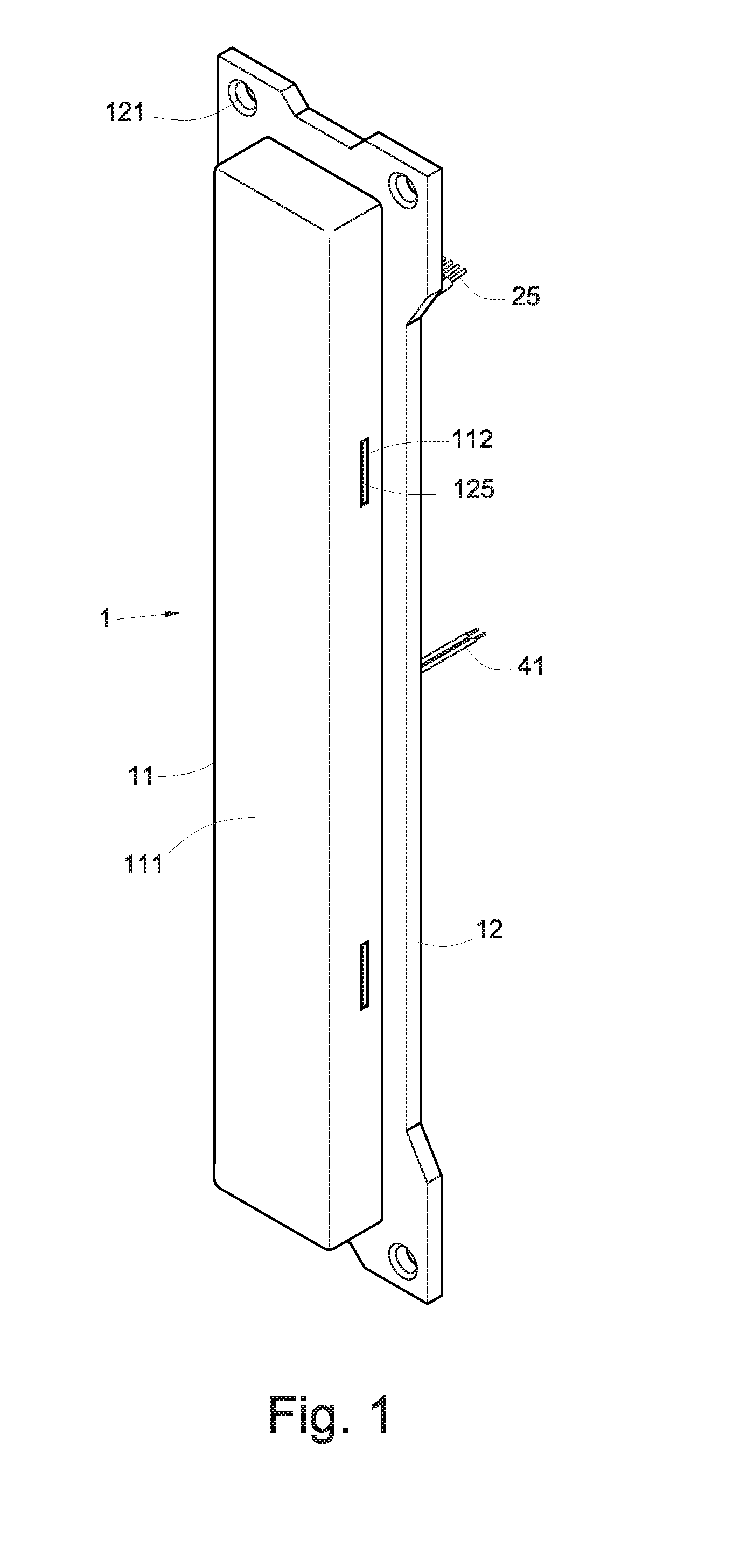
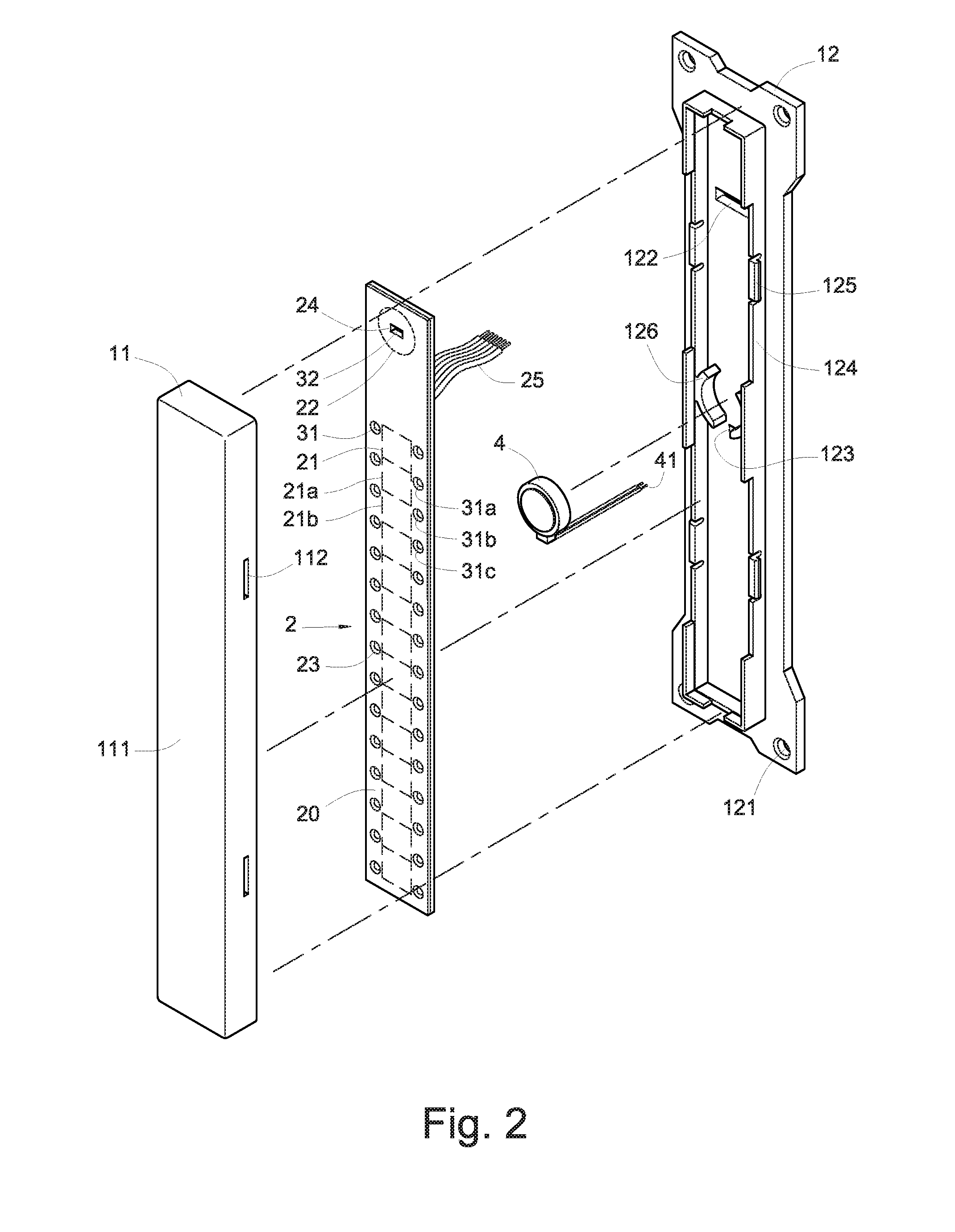
[0030]FIG. 1 is a perspective view of a preferred embodiment of the present invention. FIG. 2 is an exploded perspective view of the embodiment shown in FIG. 1. FIG. is a front view of the embodiment shown in FIG. 1.

[0031]FIG. 4 is a sectional view taken along line A-A of FIG. 3. FIG. 5 is a front view similar to FIG. 3, showing another mode of implementation. Referring to FIG. 1 to FIG. 5, a touch-sensitive linear adjustment switch according to the present invention includes a housing 1, a touch control circuit board 2, and a plurality of first light-emitting elements 31.

[0032]The housing 1 has an elongated configuration and forms a receiving groove 10 therein. The housing 1 has an outer wall serving as a light-permeable sensing surface 111 to be touched by a human hand.

[0033]The housing 1 includes a strip-shaped upper cover 11 and a strip-shaped lower cover 12. The sensing surface 111 is an outer wall of the strip-shaped upper cover 11.

[0034]The strip-shaped lower cover 12 is peri...


PUM


Abstract

A touch-sensitive linear adjustment switch is configured to be touched along a linear direction in order to turn on or off, or make stepwise adjustment to the power supplied from, an external power source. The switch includes a housing having a light-permeable sensing surface. The touch control circuit board in the housing has a touch control circuit layer adjacent to the sensing surface. The surface of the touch control circuit layer is divided into plural first sensing areas arranged along the linear direction and is provided at intervals with plural first light-emitting elements, each located beside or in one first sensing area. When touched, the sensing surface triggers the touch control circuit layer in the corresponding first sensing area to control light emission of the light-emitting element(s) beside or in the first sensing area and to output a coded signal for controlling power supply from the external power source.

Description

BACKGROUND OF THE INVENTION[0001]1. Technical Field[0002]The present invention provides a touch-sensitive linear adjustment switch. More particularly, the present invention relates to a switch designed to be touched along a linear direction in order to turn on or off an external power source or make stepwise adjustment to the magnitude of the power supplied from the external power source.[0003]2. Description of Related Art[0004]A consumer electronic product, be it a computer, a communication device, or an electric home appliance, is often equipped with rotary knobs or switches for making adjustments. Such adjustment switches are analog control elements and generally are used to switch on or off the power supply to a circuit and adjust the magnitude of the power supplied, thereby adjusting the operation speed or output power of an electric appliance, such as the rotation speed of an electric fan, the coolness of an air conditioner, the acoustic volume of a loudspeaker, the brightness...

Claims


Application Information

Patent Timeline
Patent Type & Authority Applications(United States)
IPC IPC(8): H03K17/96
CPCH03K17/9631H01H2219/014H01H2219/016H03K17/9629H03K2217/96066H01H36/00
Inventor CHU, CHING-HSIUNG
Owner CHU CHING HSIUNG
Why Eureka
Try Eureka