Drop in surgical illuminator

a surgical opening and illuminator technology, applied in the field of medical devices, systems and methods, can solve the problems of uncomfortable patients, devices are not anchored, and can easily move around and get in the way, and achieve the effect of easy repositioning and easy anchored to

Active Publication Date: 2018-06-19
INVUITY
View PDF42 Cites 30 Cited by
  • Summary
  • Abstract
  • Description
  • Claims
  • Application Information

AI Technical Summary

Benefits of technology

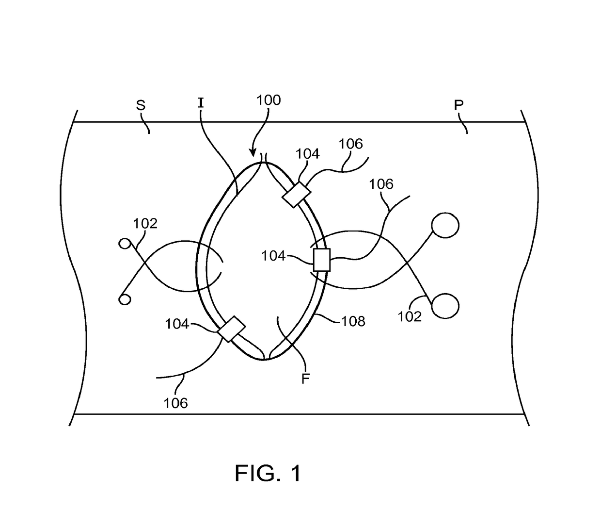
[0008]The present application generally relates to medical devices, systems and methods, and more particularly relates to illumination of a surgical field in a patient. More specifically, the present application relates to anchoring an illumination element to, or adjacent the patient so that the illumination element is easily anchored to the patient or adjacent surgical equipment without requiring anchoring to surrounding surgical instruments that may be difficult to move or anchor to, and the illumination element is easily repositionable in the surgical field.
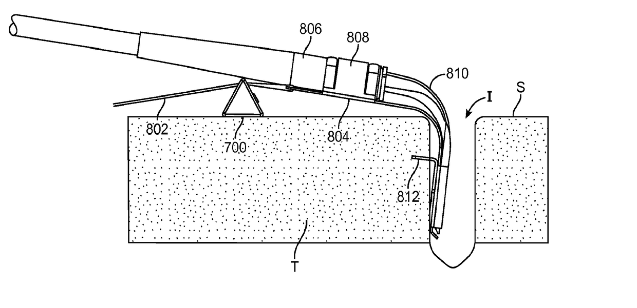
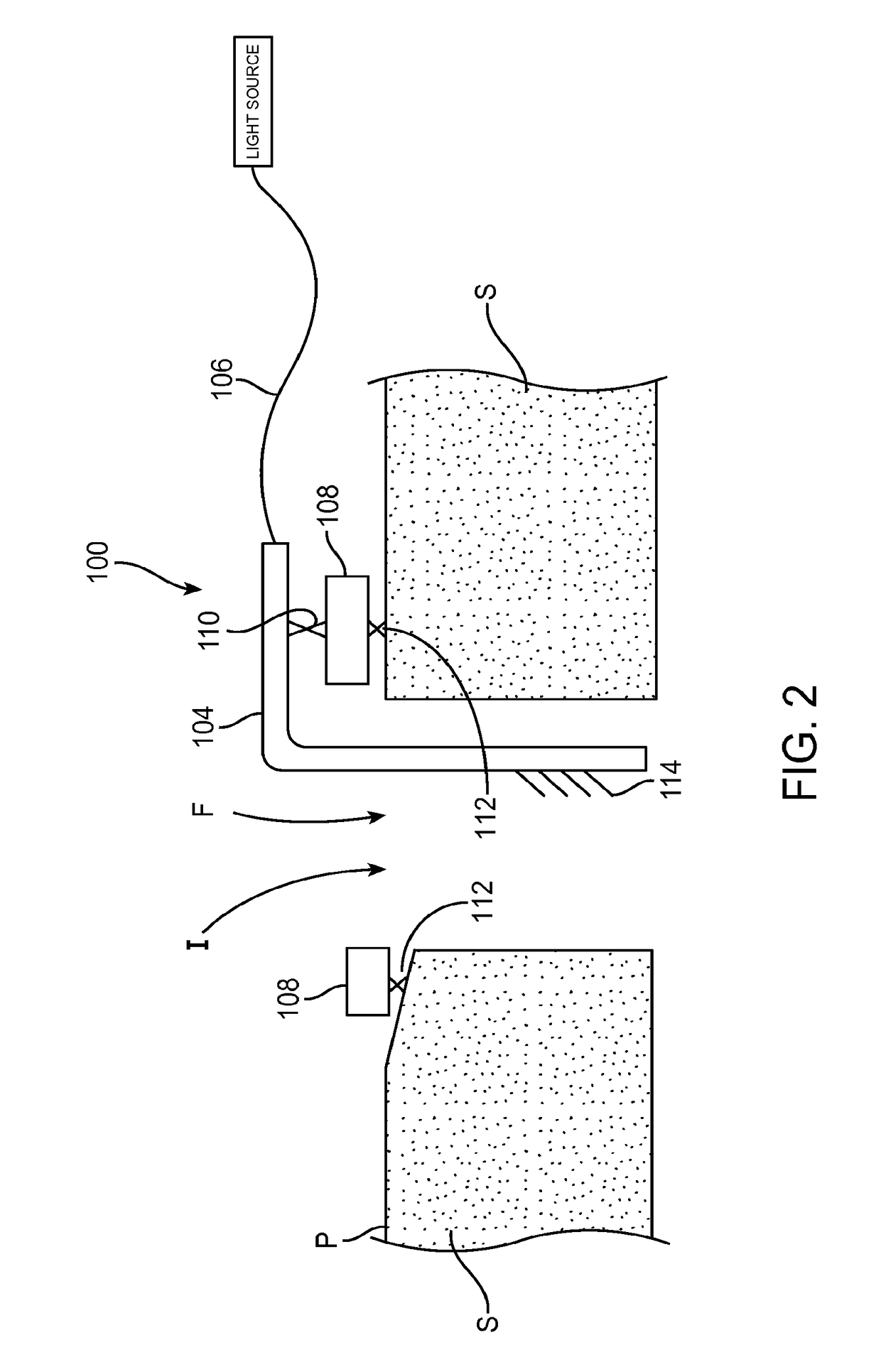
[0009]In a first aspect of the present invention, an illumination system for adjustably positioning an illumination element in a surgical field in a patient comprises an anchor element and an illumination element. The anchor element is configured to be releasably coupled with the patient, and the illumination element is coupled to the anchor element. It is possible for the anchor and illuminator element to be integral and therefore the same part that are inserted or removed together, or they may be separate components. They do not necessarily need to be detachable from one another. The anchor may comprise two anchor elements, one for anchoring in the surgical field, and the other may be for anchoring to the patient away from the incision. The illumination element may be configured to be coupled, uncoupled, and recoupled with the anchor element, thereby allowing repositioning of the illumination element at a plurality of positions in the surgical field without interfering with adjacent surgical instruments. Similarly the anchor element or the illumination element may be configured to be coupled, uncoupled, and recoupled with the patient or adjacent surgical equipment to allow repositioning of the illumination element at a plurality of positions in the surgical field without interfering with adjacent surgical instruments. Repositioning in either case allows adjustment of illumination in the surgical field. In other embodiments, the entire assembly of the illuminator and the anchor may be repositioned.
[0010]The illumination element may be configured to be coupled, uncoupled, and recoupled with the anchor element, thereby allowing repositioning of the illumination element at a plurality of positions in the surgical field without interfering with adjacent surgical instruments.
[0014]In another aspect of the present invention, a method for illuminating a surgical field in a patient comprises providing an anchor element and an illumination element, wherein the illumination element is coupled to the anchor element, and releasably attaching the anchor element to the patient or adjacent surgical equipment at a first position. The method also comprises uncoupling the illumination element from the patient or adjacent surgical equipment and moving the illumination element to a second position different than the first position. Recoupling the illumination element to the patient or the adjacent surgical equipment allows illumination of a new region of the surgical field.
[0030]The system may further comprise an imaging element that is coupled to the rear shield or the surgical tool. The imaging element may be configured to provide an image of the surgical field. The system may comprise a suction element on or in the rear shield or the surgical tool. The suction element may be a tube, channel or other structure which is configured to remove smoke or noxious fumes from the surgical field. The system may further comprise a heat sink that is thermally coupled to the rear shield. The rear shield may have a polished or lightened surface to reduce absorption of heat by the rear shield. The rear shield may have a layer of plating to increase its thermal conductivity. An insulating thermal barrier such as fluroinated ethylene propylene (FEP) may be disposed between the rear shield and the surgical tool. Any one or more of the imaging element, illumination element or suction element may be integral with the proximal or distal anchors and therefore be a single component.

Problems solved by technology

The device is not anchored and can easily move around and get in the way.
The patient must bite down on the device in order to anchor it and this can be uncomfortable for the patient.

Method used


Image

  • Drop in surgical illuminator
  • Drop in surgical illuminator
  • Drop in surgical illuminator

Examples


Embodiment Construction

[0046]Specific embodiments of the disclosed device, delivery system, and method will now be described with reference to the drawings. Nothing in this detailed description is intended to imply that any particular component, feature, or step is essential to the invention.

[0047]Surgical illuminators are often coupled to a surgical instrument such as a retractor blade or retractor frame. FIG. 4 illustrates the illumination element 206 coupled to a retractor frame 202 having blades 204. An input cable 206 such as a fiber optic cable allows light to be input from an external source to the illumination element 206.

[0048]Thus, the surgical illuminator position is fixed relative to the surgical field and this can be inconvenient for a surgeon who may require illumination of the surgical field to be adjusted during surgery, or for the illuminator to be moved to a different position in the surgical field in order to accommodate surgical instruments or a surgeon's hands. Also, the retractors ar...


PUM


Abstract

An illumination system for adjustably positioning an illuminator in a surgical field in a patient includes an anchor element and an illumination element. The anchor element is configured to be releasably coupled with the patient, and the illumination element is coupled to the anchor element. The anchor element or the illumination element is configured to be coupled, uncoupled, and recoupled with the patient or adjacent surgical equipment. This allows repositioning of the illumination element at a plurality of positions in the surgical field without interfering with adjacent surgical instruments, and further permits adjustment of illumination in the surgical field.

Description

CROSS-REFERENCE TO RELATED APPLICATIONS[0001]The present application is a non-provisional of, and claims the benefit of U.S. Provisional Patent Application No. 61 / 932,652 filed Jan. 28, 2014; the entire contents of which are incorporated herein by reference.BACKGROUND OF THE INVENTION[0002]1. Field of the Invention[0003]The present application generally relates to medical devices, systems and methods, and more particularly relates to illumination of a surgical opening during a procedure. More specifically, the present application relates to anchoring of an illumination element to the tissue, surgical draping or other adjacent surgical equipment so that the illumination element is easily anchored to tissue or surgical drapes or other adjacent surgical equipment and preferably without requiring attachment to surgical instruments such as retractor blades. This allows the illumination element to be easily positioned and repositioned in the surgical field intra-operatively without basing...

Claims


Application Information

Patent Timeline
Patent Type & Authority Patents(United States)
IPC IPC(8): A61B1/32A61B1/07A61B17/02A61B1/313A61B1/12A61B1/06A61B90/57A61B90/30A61B17/00
CPCA61B90/30A61B90/57A61B1/07A61B1/0684A61B1/128A61B1/3132A61B17/02A61B17/0218A61B17/0206A61B2017/00283A61B2017/00477A61B2017/00876A61B2017/00951A61B2017/0287A61B2090/306A61B2090/309A61B2217/005A61B2218/008
Inventor VAYSER, ALEXRIMER, DOUGLASWAYNE, DAVID
Owner INVUITY
Why Eureka
Try Eureka