Clearing obstacles

Inactive Publication Date: 2002-08-06
THE UNITED STATES OF AMERICA AS REPRESENTED BY THE SECRETARY OF THE NAVY
View PDF0 Cites 13 Cited by
  • Summary
  • Abstract
  • Description
  • Claims
  • Application Information

AI Technical Summary

Benefits of technology

to provide an improved system for clearing obstacles that overcomes the disadvantages of the prior art. Additional objects and advantages of the invention will appear from the following detailed description which, together with the accompanying drawings, discloses a preferred embodiment of the invention for purposes of illustration only. For definition of the invention, reference will be made to the appended claims.

Problems solved by technology

This may be dangerous because of the presence of antipersonnel mines or for other reasons.

Method used


Image

  • Clearing obstacles
  • Clearing obstacles
  • Clearing obstacles

Examples


Embodiment Construction

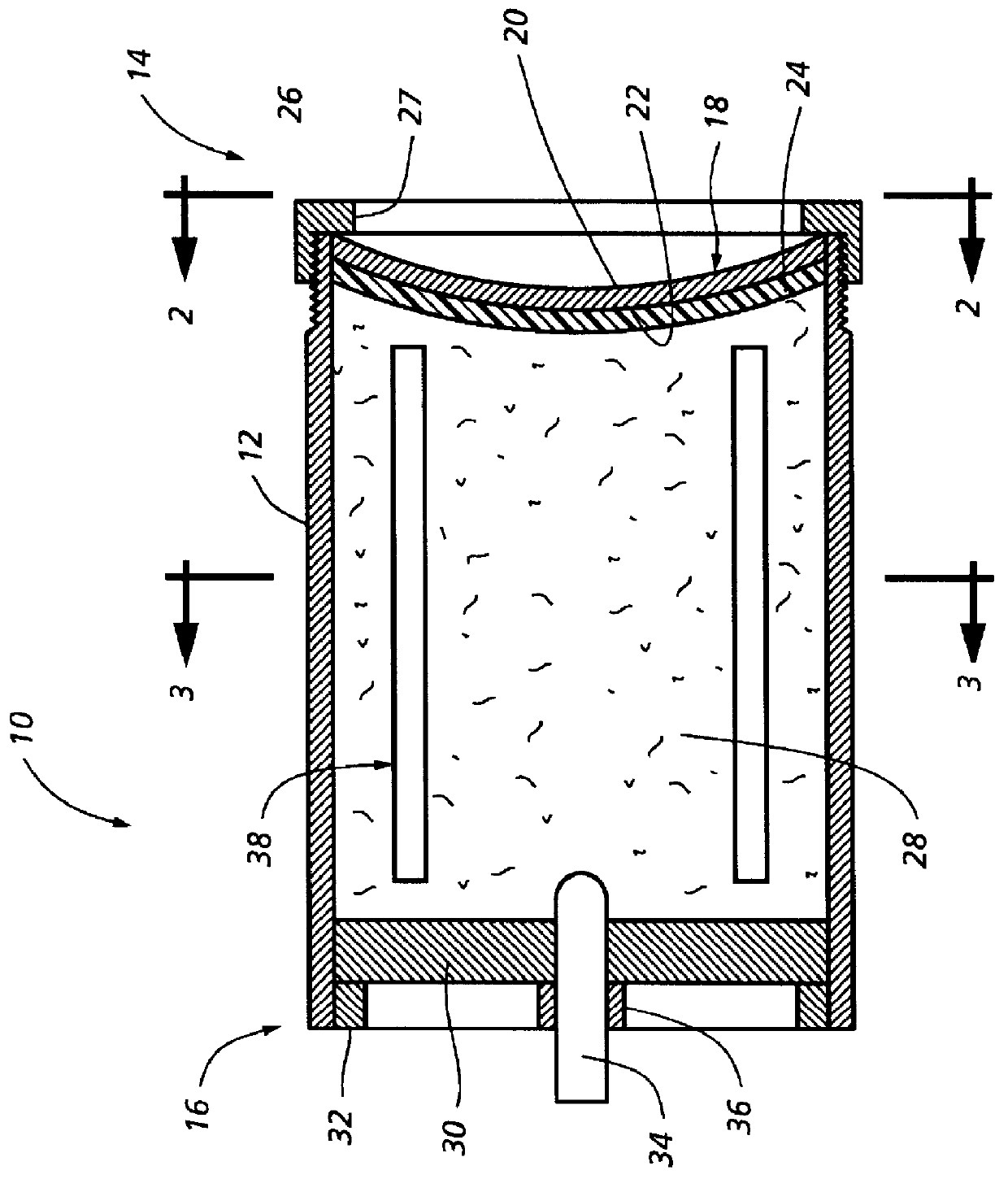
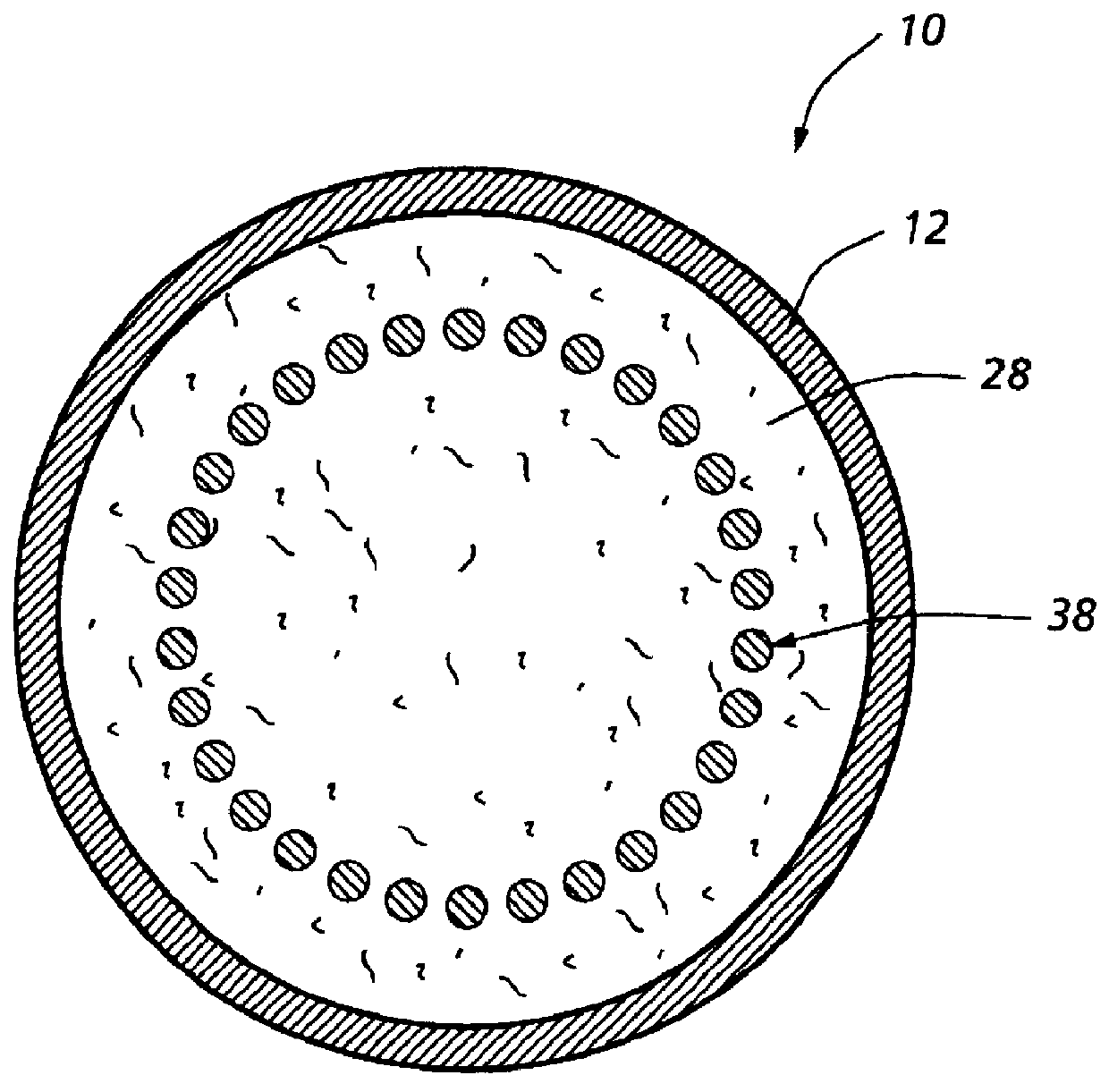
The obstacle clearing apparatus of FIGS. 1 and 2 is generally indicated at 10 and comprises a hollow cylindrical body member 12 that may take the form of a section of commercial PVC (polyvinyl chloride) pipe. Body 12 has a fore side portion 14, an aft side portion 16, and additional side portions circumferentially around the cylinder of the pipe.

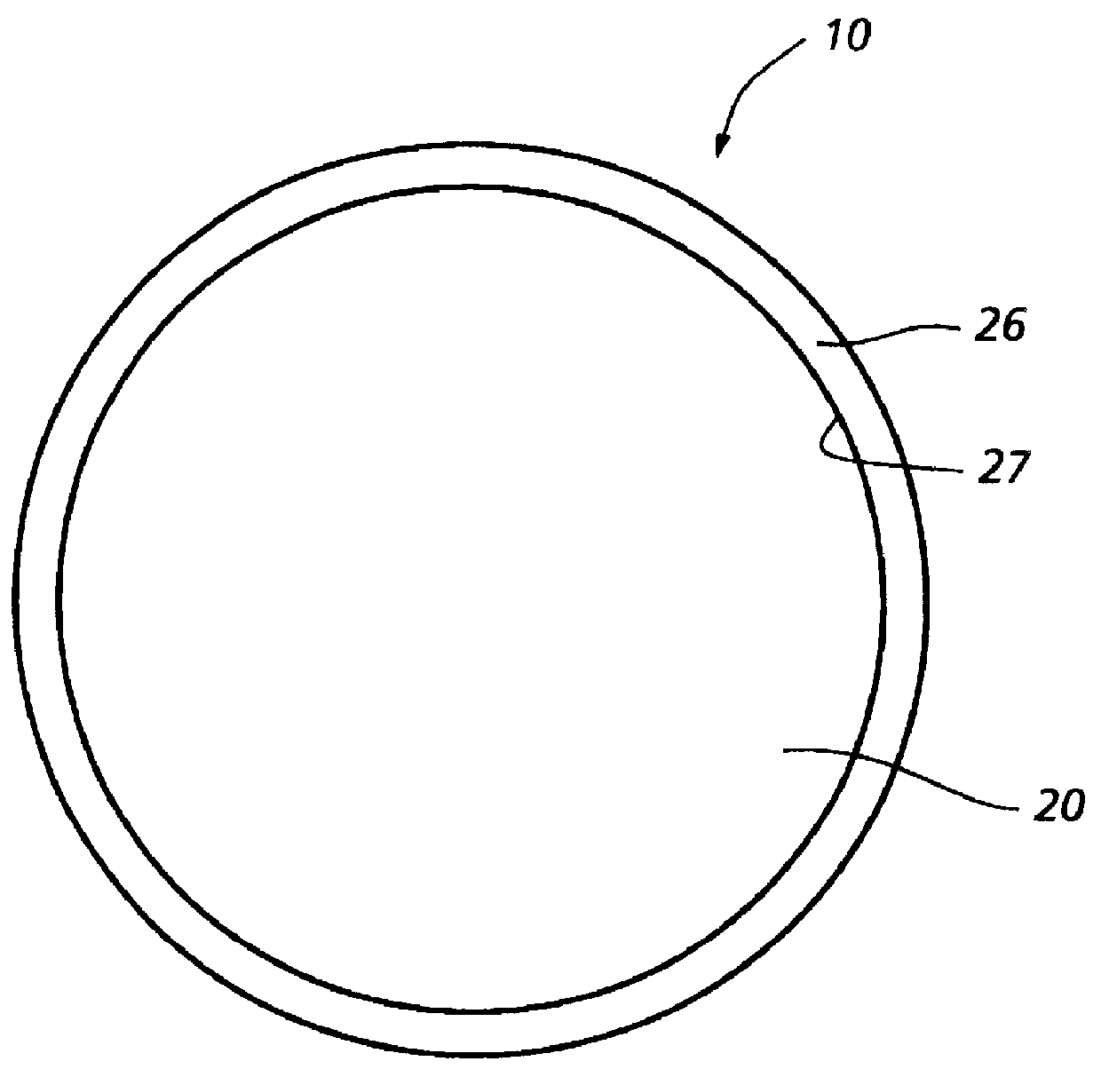
Apparatus 10 further comprises a flying metal plate member 18 mounted at the fore side portion of body 12. Flying metal plates and their power to breach holes in barriers of concrete and steel are known, see U.S. Pat. No. 5,524,546. Such plates have a concave front face 20, a convex rear face 22, and a generally uniform thickness. A layer of strong elastomeric material 24 covers rear face 22 of plate 18. Plate 18 is preferably made of copper.

Plate 18 is mounted on the fore side portion of body 12. An annular breakaway cap 26 threadedly engaged with threads formed on the outside of fore side body portion 14 has a radially inwardly projecting ...


PUM


Abstract

System for clearing both light and heavy obstacles, in which one or more flying metal plates are propelled against heavy obstacles by explosive forces which also expand a folded continous rod member into a curvilinear, generally annular configuration that cuts through light obstacles such as concertina wire in the process of unfolding.

Description

BACKGROUND OF THE INVENTIONThis invention relates to obstacle clearing or demolition using explosives.Heavy obstacles such as concrete tetrahedrons are conventionally destroyed or cleared by placing haversack charges in close proximity to the obstacle and detonating the charges. Light obstacles such as coils of barbed wire or concertina which may be intermingled with the heavy obstacles are cleared by placing bangalore torpedoes (metal tubes filled with explosive) under the wire and detonating so that the blast and fragments cut the wire. Clearing both heavy and light obstacles in the conventional way thus requires men to go into close physical proximity to the respective obstacles to place the explosive charges. This may be dangerous because of the presence of antipersonnel mines or for other reasons.It is an object of the invention to provide an improved system for clearing obstacles that overcomes the disadvantages of the prior art. Additional objects and advantages of the invent...

Claims


Application Information

Patent Timeline
Patent Type & Authority Patents(United States)
IPC IPC(8): F42B12/30F42B1/00F42B1/02F42B3/00F42B12/02
CPCF42B12/30F42B1/02F42B3/00
Inventor HOLT, WILLIAM H.ROZNER, ALEXANDER G.HOWDER, BERNARD P.
Owner THE UNITED STATES OF AMERICA AS REPRESENTED BY THE SECRETARY OF THE NAVY
Why Eureka
Try Eureka