Apparatus for glueing the tail of a web to a log formed of the web material

a technology of web material and tail, which is applied in the direction of webs handling, transportation and packaging, other domestic objects, etc., can solve the problems of a rather complex and costly structure of the glue applicator typ

Inactive Publication Date: 2001-02-06
FABIO PERINI SPA
View PDF18 Cites 22 Cited by
  • Summary
  • Abstract
  • Description
  • Claims
  • Application Information

AI Technical Summary

Problems solved by technology

However, this type of glue applicator has a rather complex and costly structure.

Method used


Image

  • Apparatus for glueing the tail of a web to a log formed of the web material
  • Apparatus for glueing the tail of a web to a log formed of the web material
  • Apparatus for glueing the tail of a web to a log formed of the web material

Examples


Embodiment Construction

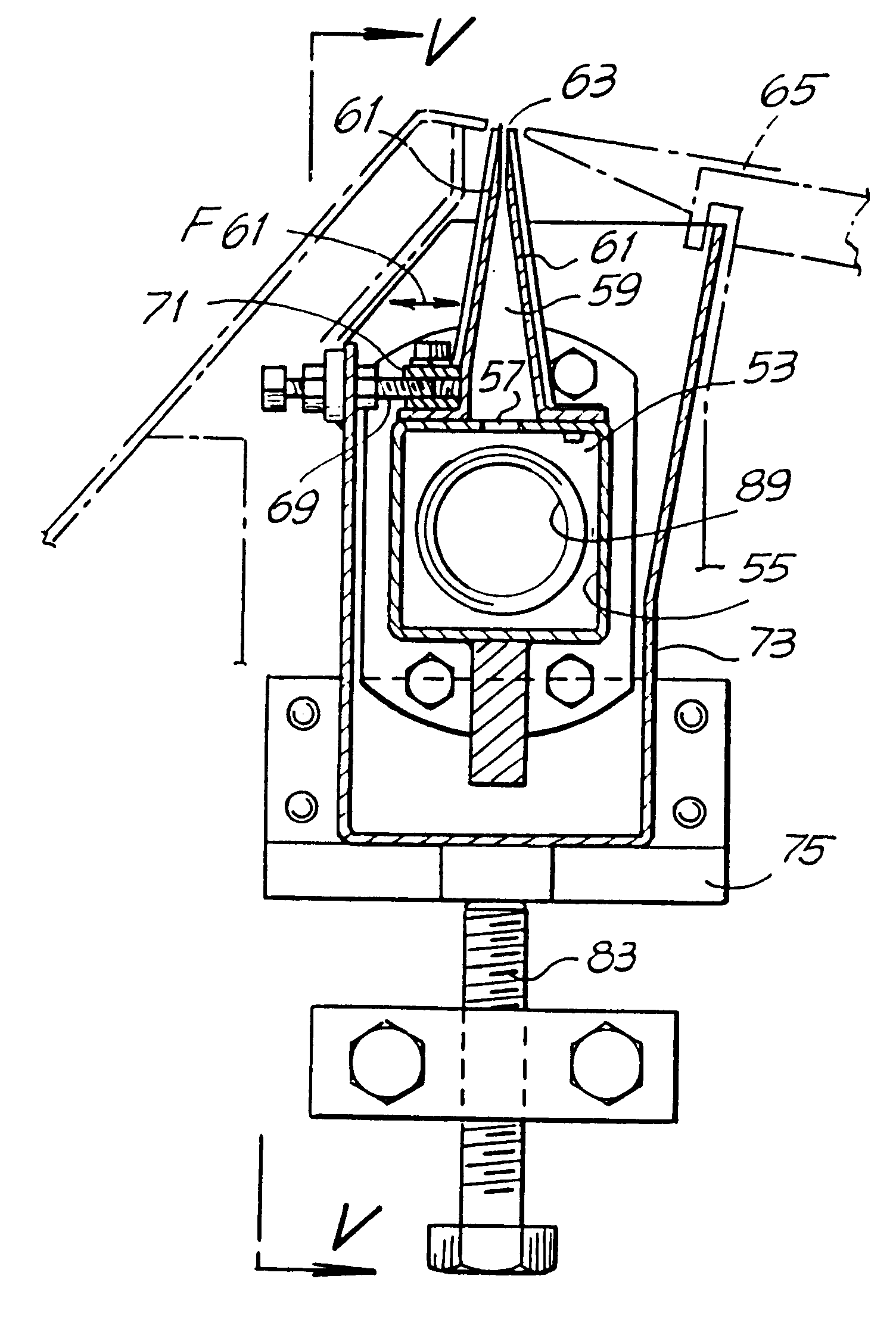
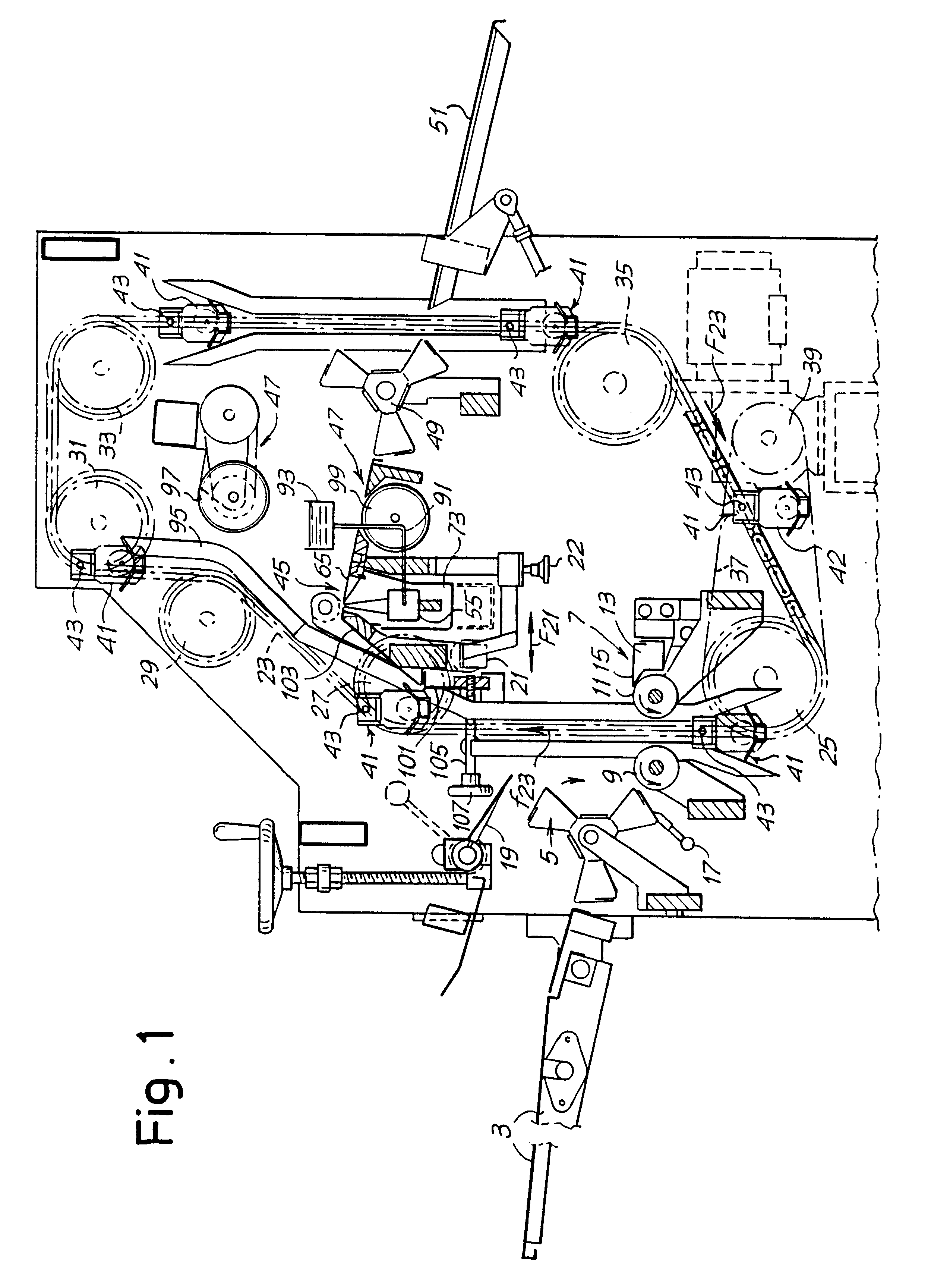
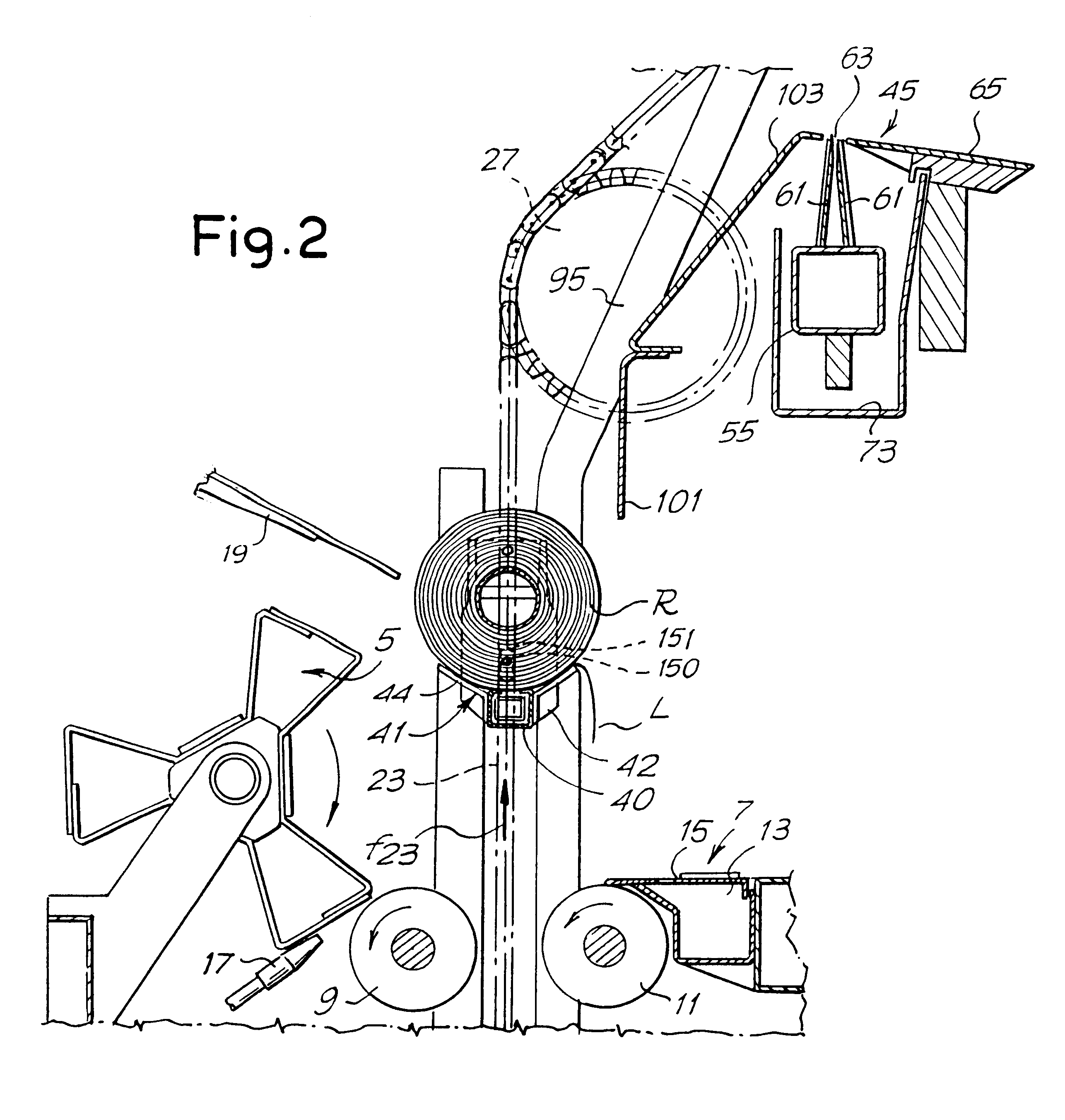
In the apparatus of the present invention, the means for applying the glue includes a dispenser device having means forming an upwardly oriented slit from which the glue is delivered by overflowing. The log transferring means discharges said log, with the tail unwound therefrom, causing it to roll over the slit while said tail is unwrapped from the log. Said slit may be of any shape. Moreover, a plurality of adjacent slits may also be provided.

In a particularly advantageous embodiment, the slit extends in a direction substantially parallel to the log axis at least for a portion of the length of the log.

With such arrangement when the log is discharged, it rolls across a guide surface and, during rolling, it passes over the slit from which the glue is continuously (or discontinuously) supplied, so that, at a predetermined location of the log surface, a strip of glue having a pattern the same as the dispensing slit is applied thereon. As the log continues to roll, the tail is automatic...


PUM

PropertyMeasurementUnit
lengthaaaaaaaaaa
widthaaaaaaaaaa
speedsaaaaaaaaaa

Abstract

An apparatus for glueing the tail or outer end of a web of material which has been formed into a log which comprises: device (9, 13) for unwinding the tail from the log (R); applicator (45) for applying glue to the log; tail rolls (97, 99) for re-winding the tail back on the log and glueing the tail to the log; and conveyor (23, 41) for transferring said log. The applicator for applying the glue includes a dispenser device (55-63) provided with a nozzle (61) forming at least one upwardly oriented slit (63) from which the glue is dispensed by overflowing; the log (R) conveyor (23, 41) discharges the log, with the tail (L) being unwound from it, above the glue dispenser, causing it to roll over said slit (63) for the application of the glue to the log.

Description

The invention refers to an apparatus for glueing the tail or outer end of a web material wound to form a roll or log. It includes means for unwinding the tail of the web of the material from a log; means for applying glue to the log; means for re-winding the tail on to the log and glueing it thereto; and means for transferring said log.BACKGROUND OF THE INVENTIONA winding apparatus of this general type is described in U.S. Pat. No. 4,475,974. That apparatus comprises chain means which support pairs of bearing rollers. The logs to be glued are disposed on these bearing rollers. Each roll or log is transported by means of a conveyor member through a first station in which the tail or outer end of the web is unwound from the log and laid down onto a flat surface. At a second station a nozzle, moving parallel to the axis of the log, applies glue to the end of the unwound material. At a third station, the log is rotated between the two bearing rollers so as to wrap the outer end and back...

Claims


Application Information

Patent Timeline
Patent Type & Authority Patents(United States)
IPC IPC(8): B05C9/00B05C5/02B05C9/02B65H19/29B65H19/22B29C65/52B29C65/78B29L7/00B65H37/04
CPCB05C5/0212B05C5/0254B05C5/0262B05C9/02B65H19/29Y10T156/1798B65H2301/414421B65H2301/414446B65H2301/41445
Inventor BIAGIOTTI, GUGLIELMO
Owner FABIO PERINI SPA
Why Eureka
Try Eureka