Method for making disposable tubular device

Inactive Publication Date: 2001-08-14
ESROCK BERNARD S
View PDF40 Cites 57 Cited by
  • Summary
  • Abstract
  • Description
  • Claims
  • Application Information

AI Technical Summary

Benefits of technology

Among the several objects of this invention may be noted the provision of an improved tubular device for conveying fluid between a medical instrument and a patient; the provision of such a device which is adapted for self-sealing to a fluid conduit of the medic

Problems solved by technology

A disadvantage encountered with prior syringe tip designs is the difficulty in having a quickly detachable tip which provides a water-tight seal between the central water passageway of the tip and a water conduit of the hand-piece.
In such syrin

Method used


Image

  • Method for making disposable tubular device
  • Method for making disposable tubular device
  • Method for making disposable tubular device

Examples


Embodiment Construction

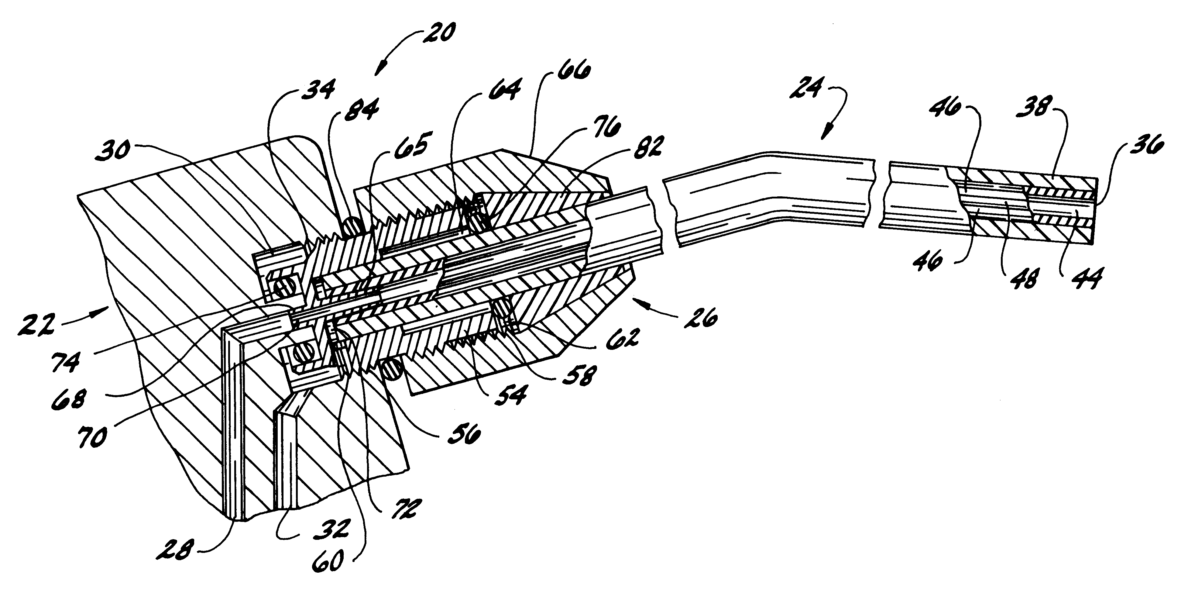
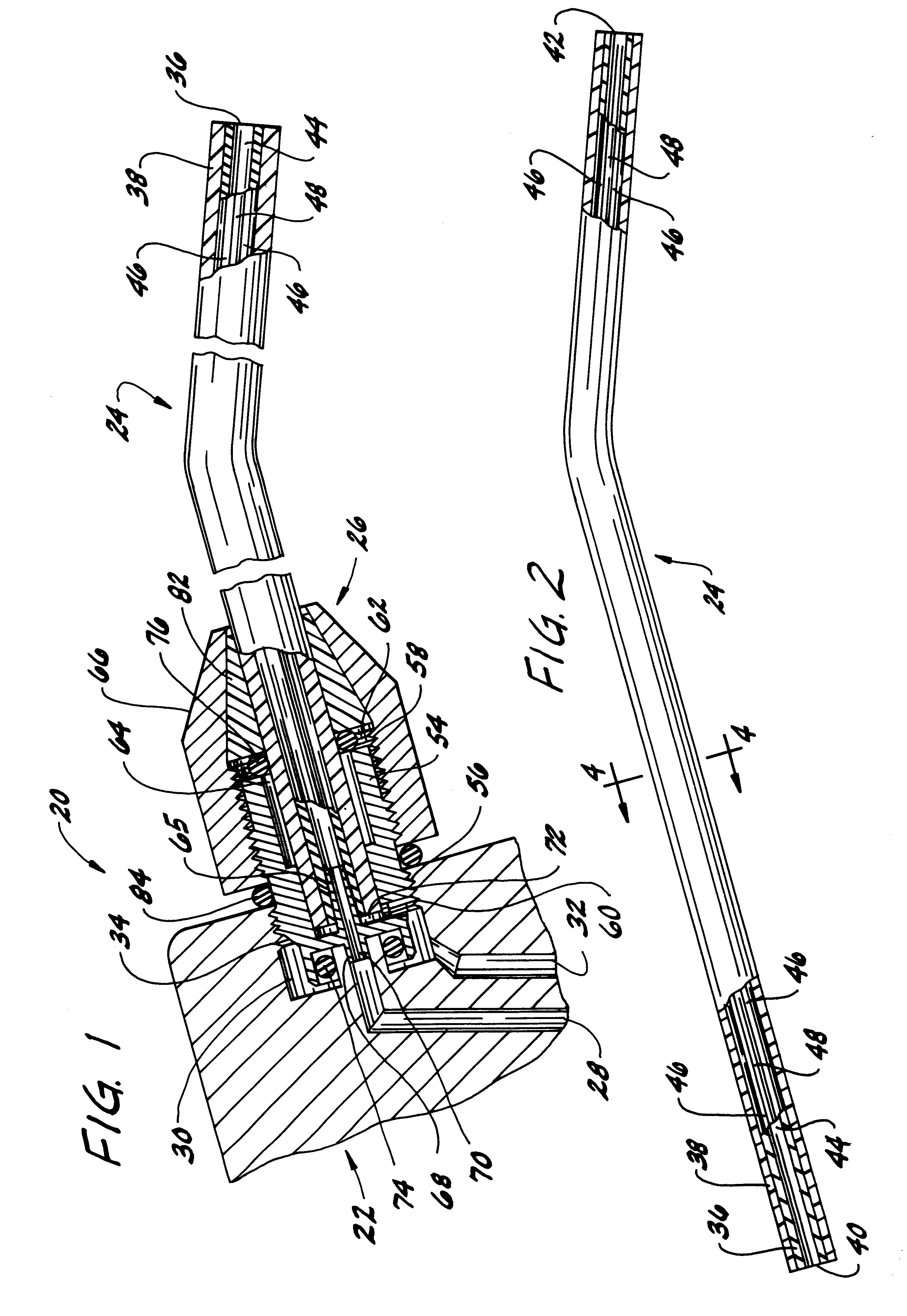
Referring now to the drawings, and first, more particularly to FIG. 1, a medical instrument of the present invention in the form of an air-water dental syringe is indicated in its entirety by the reference numeral 20. The dental syringe 20 comprises a conventional hand-piece, generally designated 22, a disposable syringe tip, generally designated 24, and a syringe tip coupler, generally designated 26, connecting the syringe tip to the hand-piece.

The hand-piece 22 includes a first fluid (water) conduit 28 for directing a stream of water to a discharge end 30 of the hand-piece and a second fluid (air) conduit 32 for directing an air stream to the discharge end of the hand-piece. The hand-piece 22 further includes a threaded bore 34 at its discharge end 30 for threadably receiving the syringe tip coupler 26. The water and air conduits 28, 32, respectively, of the hand-piece 22 extend from pressurized sources (not shown) to the bore 34 of the hand-piece and are in fluid communication th...


PUM

PropertyMeasurementUnit
Lengthaaaaaaaaaa
Stiffnessaaaaaaaaaa
Hardnessaaaaaaaaaa

Abstract

A method of making a disposable tubular device comprising extruding a first material through a first die to form the tube and moving the tube through the second die while extruding a second material through the second die to form the tube-support structure. The second material has a surface hardness which is greater than the surface hardness of the first material.

Description

BACKGROUND OF THE INVENTIONThis invention relates to disposable tubular devices of the type used with medical instruments for delivering fluid to or evacuating fluid from a patient.Tubular devices for transporting fluids between a patient and a medical instrument are typically used by medical professionals such as physicians, dentists and dental technicians, and veterinarians for suctioning fluid from or irrigating a part of a patient's body. One such tubular device is a disposable syringe tip for an air-water dental syringe.A typical syringe tip has a central water passageway and at least one passageway through which air may flow. The tip is typically sealingly retained in a syringe hand-piece by a retaining collar which compresses an O-ring against the tip to seal the connection between the tip and the handpiece. Between uses of the syringe, the tip must be removed from the hand-piece by wholly or partially disengaging the retaining collar. The tip is then either sterilized before...

Claims


Application Information

Patent Timeline
IPC IPC(8): A61C17/02A61C17/00
CPCA61C17/0217
Inventor ESROCK, BERNARD S.
Owner ESROCK BERNARD S
Why Eureka
Try Eureka