Single-cam compound archery bow

a compound archery bow and single-cam technology, applied in the field of single-cam compound archery bows, can solve the problems of affecting the accuracy of the bow, not disclosing any means or techniques for adjusting the draw length of the bow, and less than the optimal performance of the bow, so as to reduce twisting forces, reduce lateral separation, and facilitate the effect of manufacturing and servi

Inactive Publication Date: 2002-02-12
DARLINGTON REX F
View PDF17 Cites 38 Cited by
  • Summary
  • Abstract
  • Description
  • Claims
  • Application Information

AI Technical Summary

Benefits of technology

In the preferred embodiments of the invention, the power cam comprises a cam base that includes the second bow string take-up groove, and a plurality of modules mountable on the base to provide power cable grooves of differing adjustable lengths. Each module is thus both selectively mountable/demountable on the cam base and adjustably positionable on the cam base for obtaining adjustable draw length over a wide draw length range. Each module has facility for affixing the anchor point of the control cable so as to maintain a fixed spacing between such anchor point and the associated power let-off point of each module. Thus, bow string draw length is adjustable over a wide range without in any way affecting other design capabilities of the bow, including particularly straight-line movement of the draw string nock point. In the preferred embodiment of the invention, the power cable segment, the control cable segment and the bow string cable segment are provided as separate lengths of cable stock, as distinguished from a continuous length of cable stock which is less preferred. In this way, the cable segments may be provided in standard lengths, which greatly facilitates economy of both manufacture and service. The bow power cam, specifically the adjustable/replaceable draw

Problems solved by technology

A problem inherent in dual-cam bows of this type lies in the fact that the cams must be closely matched and synchronized with each other in order to insure straight-line (or substantially straight-line) travel of the nock point on the bow string, and the limbs must be closely balanced and evenly stressed as the string is drawn.
Damage to or mismatching of the cams, mismatch or incorrect adjustment of the limbs, or stretching of the cable sections can cause loss of synchronization between the cams and uneven stressing of the limbs, resulting in less than optimum performance of the bow.
In particular, the noted application does not disclose any means or techniq

Method used


Image

  • Single-cam compound archery bow
  • Single-cam compound archery bow
  • Single-cam compound archery bow

Examples


Embodiment Construction

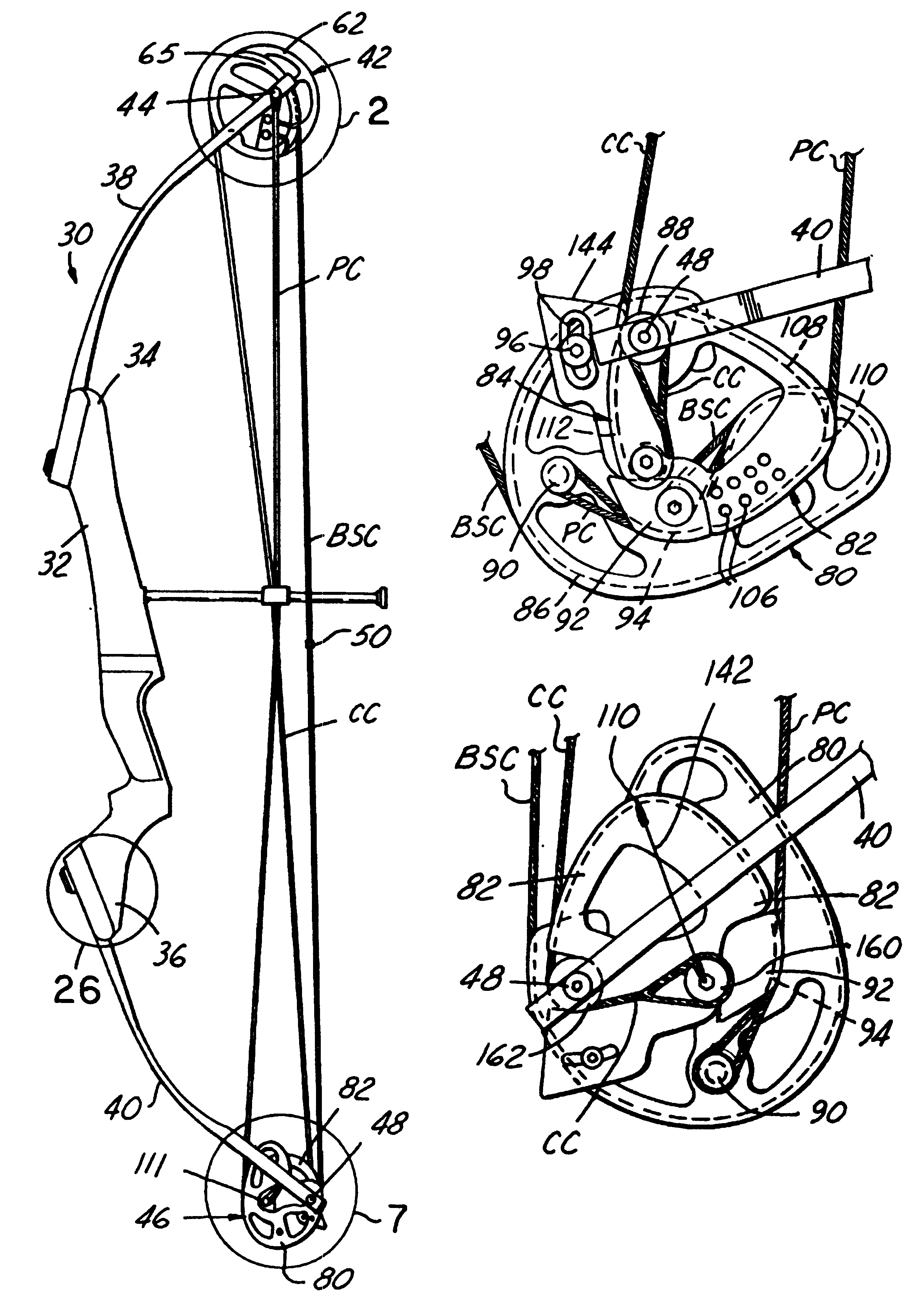
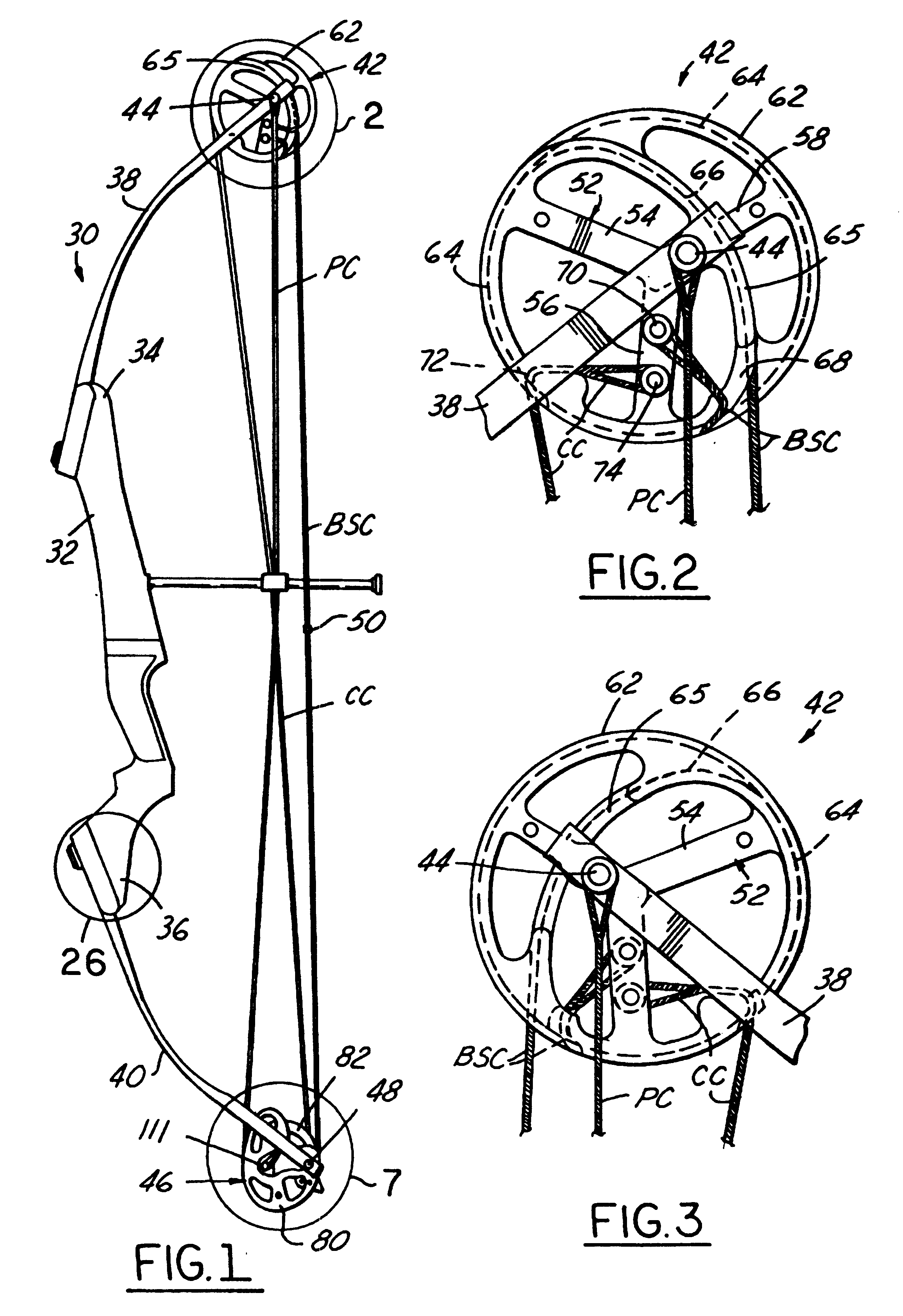
FIG. 1 illustrates a single-cam compound archery bow 30 in accordance with a presently preferred embodiment of the invention as comprising a handle 32 of cast magnesium or other rigid unitary construction having spaced ends 34, 36 with flat limb-mounting surfaces at each end. A pair of flexible limbs 38, 40 of fiber-reinforced resin or other suitable resilient construction are mounted on handle ends 34, 36 respectively, and project therefrom away from handle 32. A control wheel 42 is rotatably mounted on an axle 44 that extends laterally across the free end of bow limb 38, such that control wheel 42 is rotatably mounted within an open notch at the free end of limb 38. Likewise, a power cam 46 is rotatably mounted on an axle 48 that extends laterally across the free end of limb 40, such that power cam 46 is rotatably mounted within a notch 50 (FIG. 9) at the free end of limb 40. A power cable PC has a split end that is anchored to limb 38 at axle 44, preferably although not necessari...


PUM


Abstract

A single-cam compound archery bow that includes a bow handle from which bow limbs project, a control wheel rotatably mounted on one end of one limb and a power <DEL-S DATE="20020212" ID="DEL-S-00001">can<DEL-E ID="DEL-S-00001"> <INS-S DATE="20020212" ID="INS-S-00001">cam <INS-E ID="INS-S-00001">rotatably mounted at an opposing end of the other limb. A power cable segment is anchored at one end to the one limb and at a second end to the power <DEL-S DATE="20020212" ID="DEL-S-00002">can<DEL-E ID="DEL-S-00002"> <INS-S DATE="20020212" ID="INS-S-00002">cam <INS-E ID="INS-S-00002">at a position to wrap into and unwrap from a power cable groove on the power cam. A bow string cable segment is anchored to the control wheel and to the power cam at positions to wrap into and unwrap from first and second bow string take-up grooves on the control wheel and power cam respectively. The bow string cable segment has a nock point disposed between the spaced limb ends. A control cable segment is anchored at one end to the control wheel at a position to wrap into and unwrap from a control groove on the control wheel, and is anchored at an opposing end to the power cam. As the bow string cable segment is drawn away from the handle, the bow string cable segment unwraps equally from the control wheel and power cam, wraps the power cable segment into the power cable groove on the power cam so as to draw the bow limb ends together up to a power let-off point at the power cable groove, and wraps the control cable segment into the control groove on the control wheel. Length of the power cable groove on the power cam, and position of the power let-off point on the power cam, are adjustable while maintaining a fixed separation between the power let-off point and the control cable anchor on the power cam, so that the nock point travels in a straight line as the bow string cable section is drawn and released independent of adjusted length of the power cable groove and position of the power let-off point.

Description

The present invention is directed to compound archery bows, and more particularly to a so-called single-cam compound archery bow having a power let-off cam mounted on the end of only one of the bow limbs.BACKGROUND AND OBJECTS OF THE INVENTIONCompound archery bows typically are of the so-called dual-cam design, originated in U.S. Pat. No. 3,486,495. Bows of this type typically comprise a bow handle having limbs mounted on and extending from opposed ends of the handle. Power let-off cams are rotatably mounted on the free ends of the bow limbs and are interconnected by one or more cable sections including a draw string section. As the bow draw string is drawn away from the handle, draw force initially increases as the limbs are drawn together and the cams rotate to a power let-off point, and thereafter the leverage increases and the draw force decreases as the cams rotate further but with little additional limb flexure. This so-called compound action allows full bow draw to be maintai...

Claims


Application Information

Patent Timeline
IPC IPC(8): F41B5/00F41B5/10
CPCF41B5/10F41B5/105
Inventor DARLINGTON, REX F.
Owner DARLINGTON REX F
Why Eureka
Try Eureka