Method and apparatus for removing image forming substance from image holding member forming processing situation mark

Inactive Publication Date: 2002-04-09
RICOH KK
View PDF162 Cites 36 Cited by
  • Summary
  • Abstract
  • Description
  • Claims
  • Application Information

AI Technical Summary

Benefits of technology

It is therefore an object of the present invention to provide a method and an apparatus for removing an image forming substance from an image holding member in which a processing situation mark showing a processing situation of image forming substance removal is formed in the image holding member and hysteresis of the image holding member is known by using this processing situation mark so that a process condition of the image holding member can be suitably set at a time of the next image forming substance removing processing.

Problems solved by technology

Therefore, when the image forming substance is removed, paper fibers on the image, holding member surface are removed therefrom together with the image forming substance so that the image holding member is damaged and a paper quality is reduced.
In particular, when the image holding member is heated and pressurized through the above ink separating member, the endless sheet or the above rollers to improve removal of the image forming substance, a fixing property between the image forming substance and the image holding member is conversely increased in various kinds of conditions so that it is difficult to remove the image forming substance from the image holding member.
When the image holding member is repeatedly used by this image forming substance removing processing, there is a fear of damaging the image holding member when the number of repetitions of the image forming substance removing processing is increased.
When the image holding member is repeatedly used by the image forming substance removing processing, there is a fear of changing an optimum process condition of the image forming substance removal to the image holding member by hysteresis of the image forming substance removing processing.

Method used


Image

  • Method and apparatus for removing image forming substance from image holding member forming processing situation mark
  • Method and apparatus for removing image forming substance from image holding member forming processing situation mark
  • Method and apparatus for removing image forming substance from image holding member forming processing situation mark

Examples


Embodiment Construction

The preferred embodiments of a method and an apparatus for removing an image forming substance from an image holding member forming a processing situation mark in the present invention will next be described in detail with reference to the accompanying drawings.

In the following description, the present invention is applied to an image forming substance removing apparatus as an embodiment in which an image is formed on a sheet of transfer paper as an image holding member by an electrophotographic copying machine of a transfer type and thermally melted toner as an image forming substance is removed from the transfer paper sheet. In the following description, the image forming substance removing apparatus is called a toner removing apparatus.

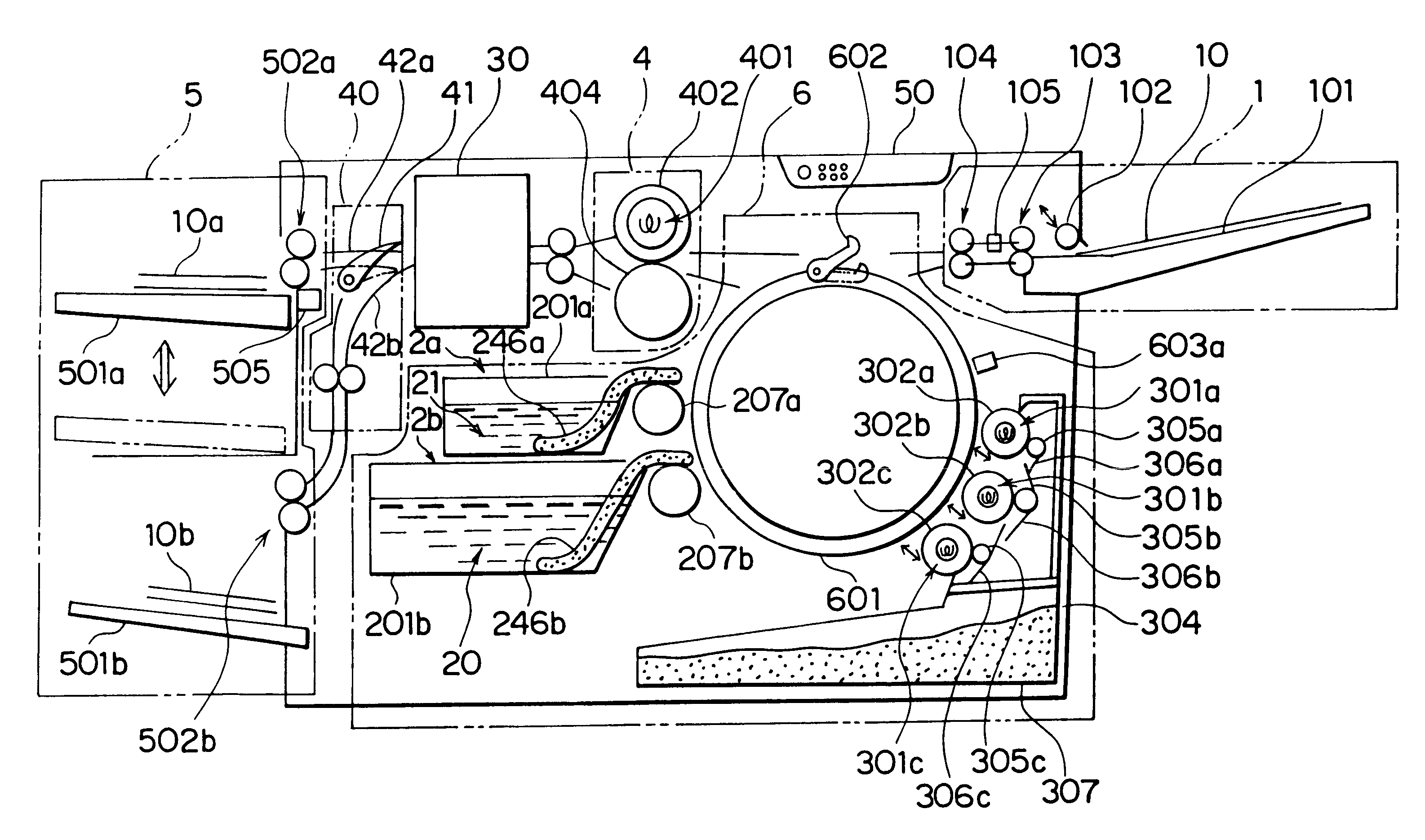
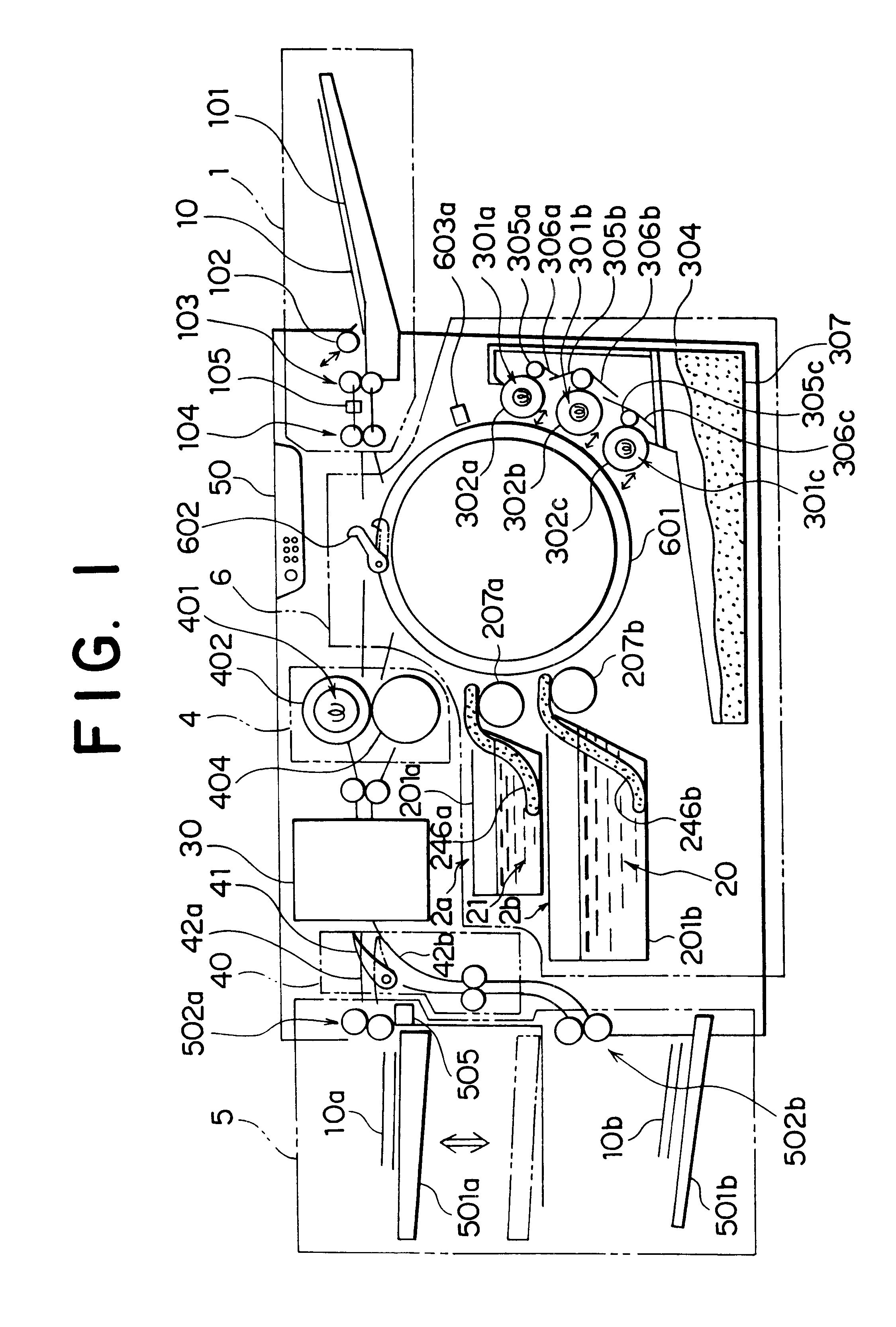
FIG. 1 is a front view showing the schematic construction of a toner removing apparatus in accordance with an embodiment of the present invention.

The entire construction of the toner removing apparatus will first be explained. This toner removing a...


PUM


Abstract

In a method and an apparatus for removing an image forming substance such as toner from an image holding member such as a sheet of transfer paper, an unstabilizing agent is provided to the image holding member. An attaching state between the image forming substance and the image holding member stably attaching the image forming substance on a surface thereof is changed to an unstable state by the unstabilizing agent. The image forming substance is separated and removed from the image holding member by making a separating member come in close contact with the image forming substance on the image holding member having the provided unstabilizing agent. A processing situation mark showing a processing situation of removal of the image forming substance is formed in the image holding member. The processing situation mark can be removed from the image holding member by the image forming substance removing processing.

Description

BACKGROUND OF THE INVENTION1. Field of the InventionThe present invention relates to a method and an apparatus for separating and removing an image forming substance from an image holding member onto which the image forming substance is stably attached by an image forming apparatus such as a copying machine, a facsimile telegraph, a printer, etc.2. Description of the Related ArtThere are generally various kinds of known methods and apparatuses for removing an image forming substance such as toner from a sheet of paper as a recorded image holding member. For example, Japanese Patent Application Laying Open (KOKAI) No. 1-101578 shows an image forming substance removing method using a solvent. In this image forming substance removing method, a sheet of paper attaching toner thereon is dipped into a soluble solvent of toner resin and a supersonic wave is vibrated in this paper sheet so that the toner dissolved into the solvent is separated from a paper face. Japanese Patent Application ...

Claims


Application Information

Patent Timeline
IPC IPC(8): B41M7/00G03G21/00
CPCB41M7/0009G03G21/00
Inventor TAKAHASHI, YASUHIROMIYASHITA, YOSHIAKISHINGURYOU, SATOSHIKURAMOTO, SHINICHIASABA, YOUICHITANIKAWA, KIYOSHITAKAHASHI, SADAOKIMURA, YOSHIYUKIANDO, KAZUHIROSAITOH, TADASHI
Owner RICOH KK
Why Eureka
Try Eureka