Golf club

a technology of golf club and ball, which is applied in the field of golf clubs, can solve the problems of unrecoverable energy put into the hands from twisting the club, unsuitable for golf clubs, and inability to transfer the energy to the ball with conventional clubs, so as to improve the performance of the club and minimize the effect of energy loss

Inactive Publication Date: 2005-03-22
PARALLEL AXIS GOLF
View PDF24 Cites 31 Cited by
  • Summary
  • Abstract
  • Description
  • Claims
  • Application Information

AI Technical Summary

Benefits of technology

The golf club disclosed and claimed herein, on the other hand, is of such construction that it minimizes energy loss due to twisting. This is believed to account for the improved performance of the club disclosed an

Problems solved by technology

Added club weight can be undesirable under many circumstances for many golfers.
The result of this is that energy put into the ha

Method used


Image

  • Golf club
  • Golf club
  • Golf club

Examples


Embodiment Construction

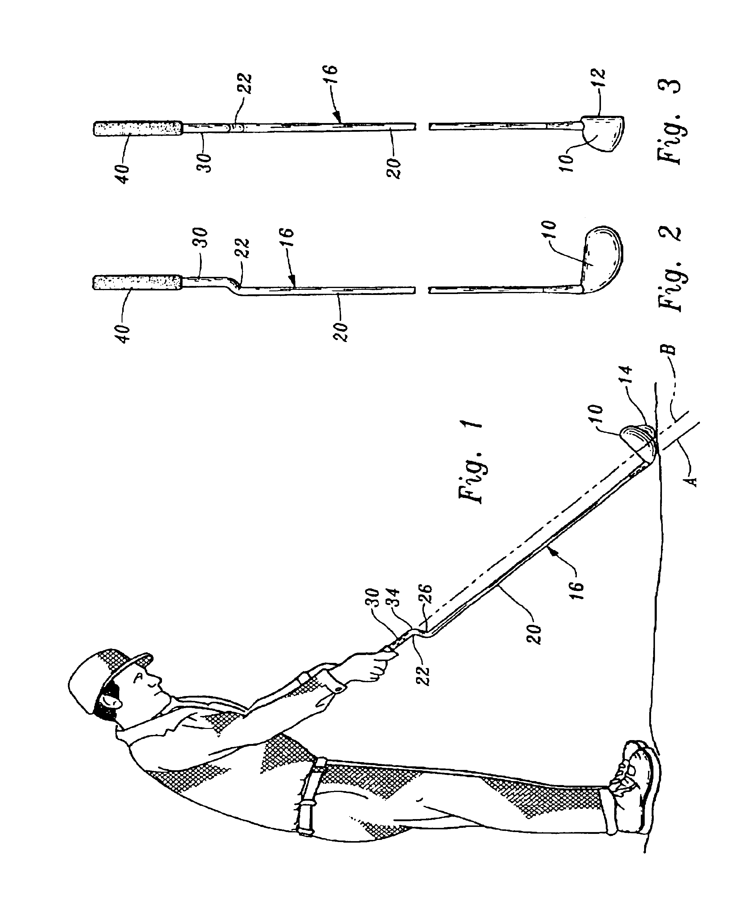
Referring now to FIGS. 1-6, a golf club constructed in accordance with the teachings of the present invention includes a club head 10 having a substantially planar golf ball engaging surface 12 (FIG. 3). In FIG. 1 a player is shown holding the club and addressing a golf ball 14.

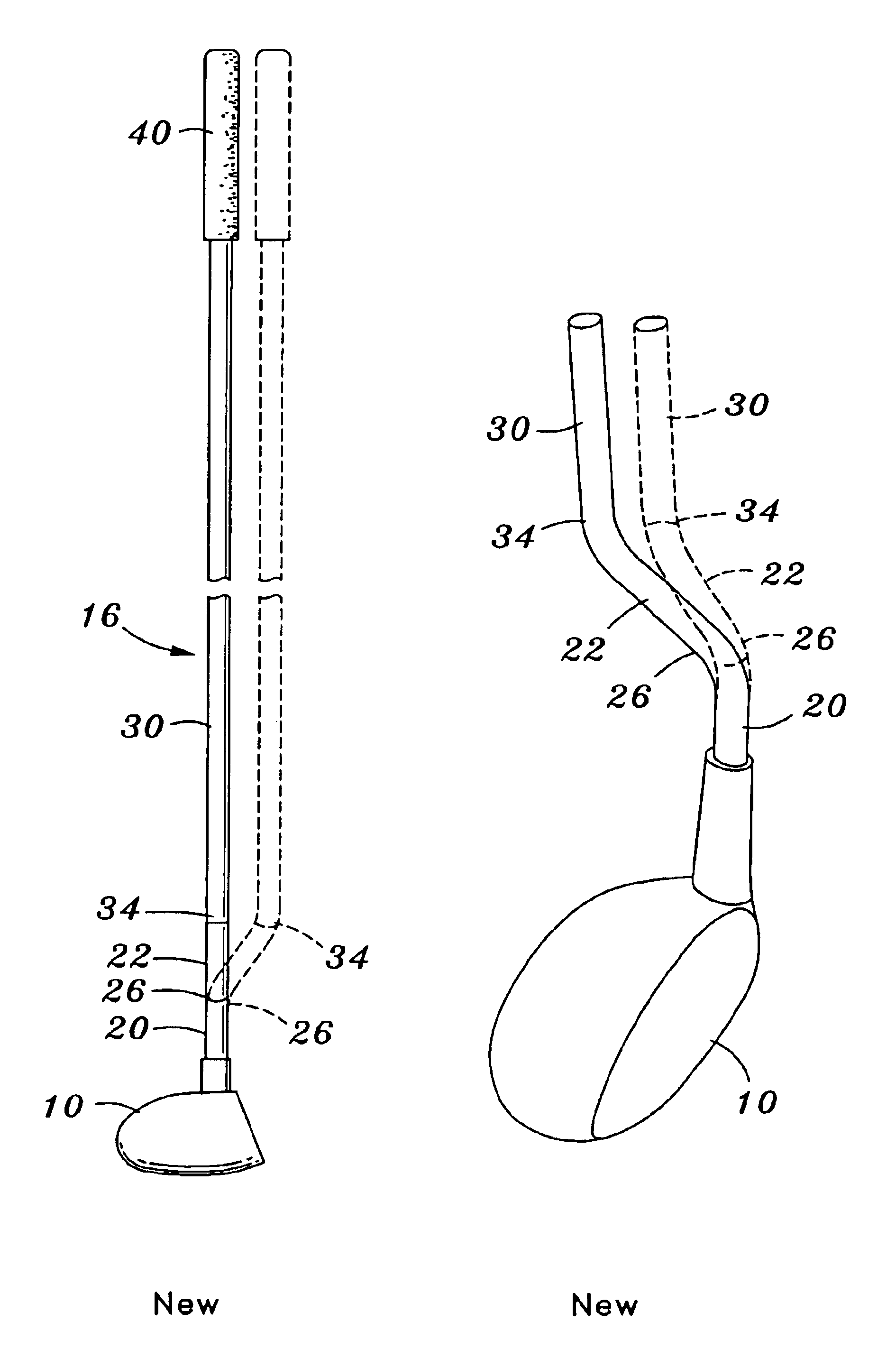
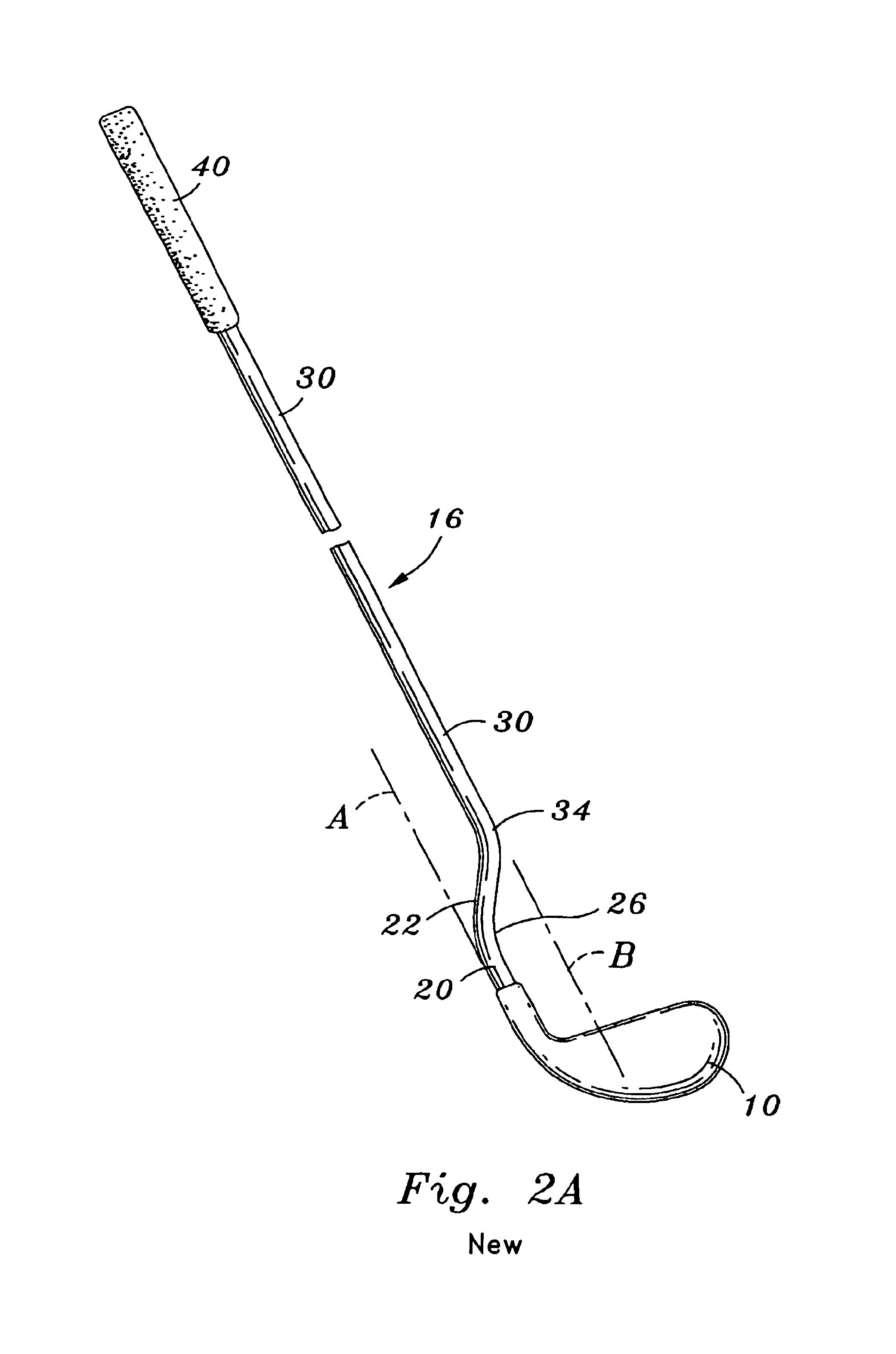
A club shaft 16 is attached to the club head and extends upwardly therefrom. Club shaft 16 includes a straight first club shaft segment 20 extending upwardly from the club head along a first imaginary line A.

A straight second club shaft segment 22 adjoins and is integrally connected to the first club shaft segment at a lower bend 26. The second club shaft segment extends upwardly from and laterally relative to the first club shaft segment from the lower bend and defines an angle of divergence Y (See FIG. 35) with the first club shaft segment at the lower bend.

A straight third club shaft segment 30 adjoins and is connected to the second club shaft segment at an upper bend 34 spaced from the first club shaft se...


PUM


Abstract

A golf club includes a club head and a club shaft attached to the club head. A plurality of bends which are spaced from one another are formed in the club shaft to define a straight first club shaft segment, a second club shaft segment adjoining and connected to the first club shaft segment extending upwardly from and laterally relative to the first club shaft segment, and a third club shaft segment adjoining and connected to the second club shaft segment and extending upwardly from the laterally relative to the second club shaft segment. The first club shaft segment and the third club shaft segment extend along spaced imaginary lines and the club head is closer to the golfer swinging the golf club than would be the case if the club shaft were straight along the length thereof.

Description

TECHNICAL FIELDThis invention relates to a golf club which is so constructed as to provide improved performance compared to conventional golf club constructions. In particular, the golf club of the present invention enables a golfer to hit a golf ball longer and straighter as compared to convectional golf club constructions.BACKGROUND ARTGolf clubs typically employ shafts which are straight between the club head and the club handle. A wide variety of materials have been and are employed in the construction of such shafts.Golf clubs, particularly putters, have been proposed which employ shafts which are not straight in an attempt to improve club performance. The clubs shown in the following U.S. patents are believed to be representative of the state of the art insofar as non-straight club shafts are concerned: U.S. Pat. Nos. 3,874,668, issued Apr. 1, 1975, U.S. Pat. DES. 256,824, issued Sep. 9, 1980, U.S. Pat. No. 4,227,694, issued Oct. 14, 1980, U.S. Pat. No. 4,625,965, issued Dec. ...

Claims


Application Information

Patent Timeline
IPC IPC(8): A63B53/00A63B53/14A63B53/10A63B53/02A63B53/16
CPCA63B53/007A63B53/10A63B53/14A63B60/06A63B60/08A63B60/10A63B60/22A63B60/34A63B53/005A63B53/021A63B60/00
Inventor BOTHWELL, CHARLES R.
Owner PARALLEL AXIS GOLF
Why Eureka
Try Eureka