Safety trip assembly and trip lock mechanism for a fastener driving tool

Inactive Publication Date: 2005-10-18
STANLEY FASTENING SYST LP
View PDF18 Cites 13 Cited by
  • Summary
  • Abstract
  • Description
  • Claims
  • Application Information

AI Technical Summary

Benefits of technology

[0015]The fastener magazine assembly is constructed and arranged to engage the trip lock mechanism when the fastener magazine assembly is attached to the housing assembly to move the trip lock member against the biasing force to the neutral orientation. The trip lock member is constructed and arranged to move the locking orientation under the biasing force when the fastener magazine assembly is removed from the housing to prevent the

Problems solved by technology

When no fastener is present in the drive track when the driving mechanism is actuated, for example, the driving device must absorb all of the energy generated during the drive stroke and this subjects the device to an undesirable level of stress.
It is also undesirable to actuate the driving mechanism when no fastener is in the drive track and the nosepiece is against the workpiece because the driving element typically extends out of the nosepiece when the driver is at the lowermost point of its power stroke so that the fastener can be drive flush or countersunk in the workpiece.
Thus, if no fastener is present in th

Method used


Image

  • Safety trip assembly and trip lock mechanism for a fastener driving tool
  • Safety trip assembly and trip lock mechanism for a fastener driving tool
  • Safety trip assembly and trip lock mechanism for a fastener driving tool

Examples


Embodiment Construction

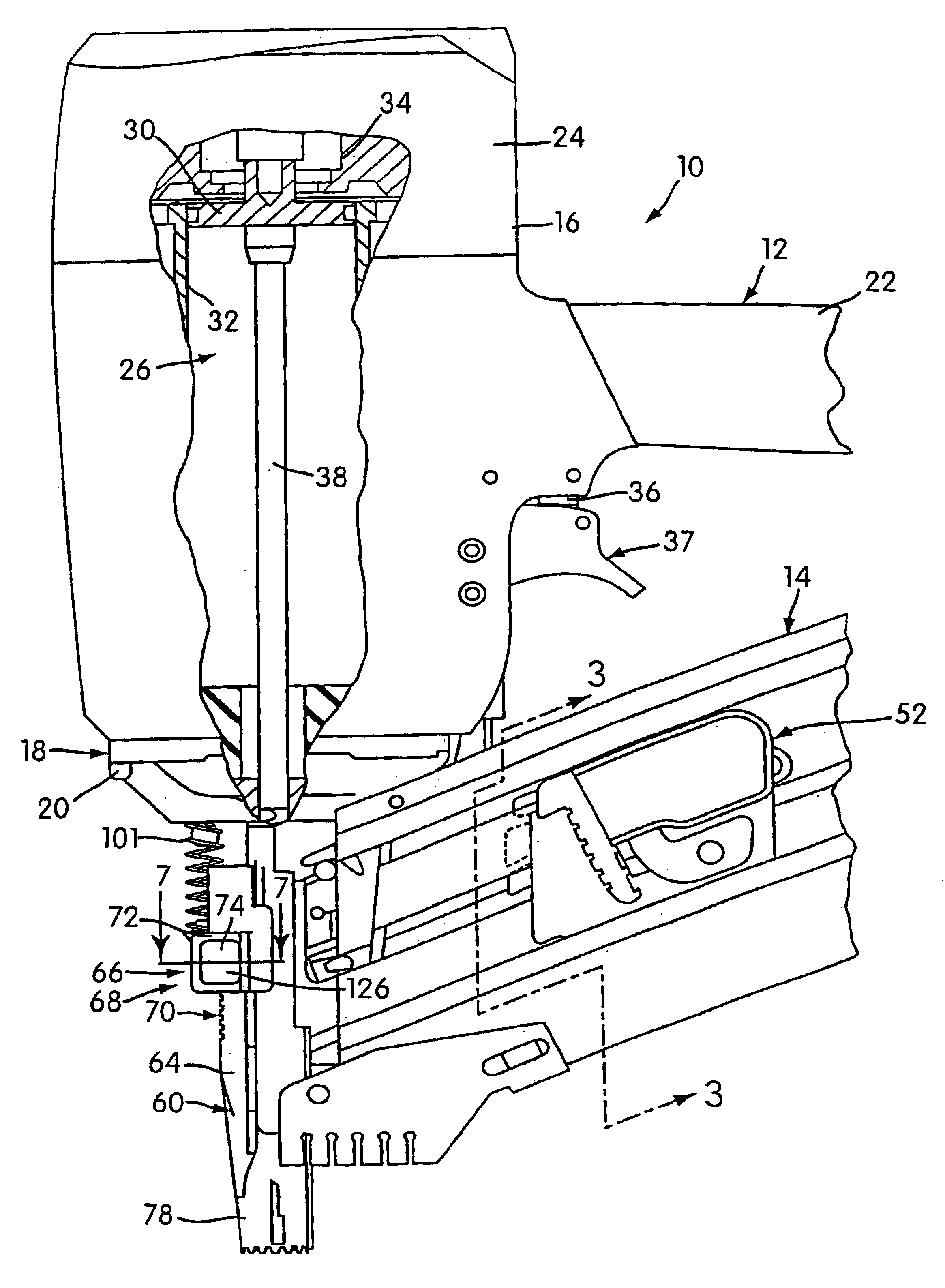
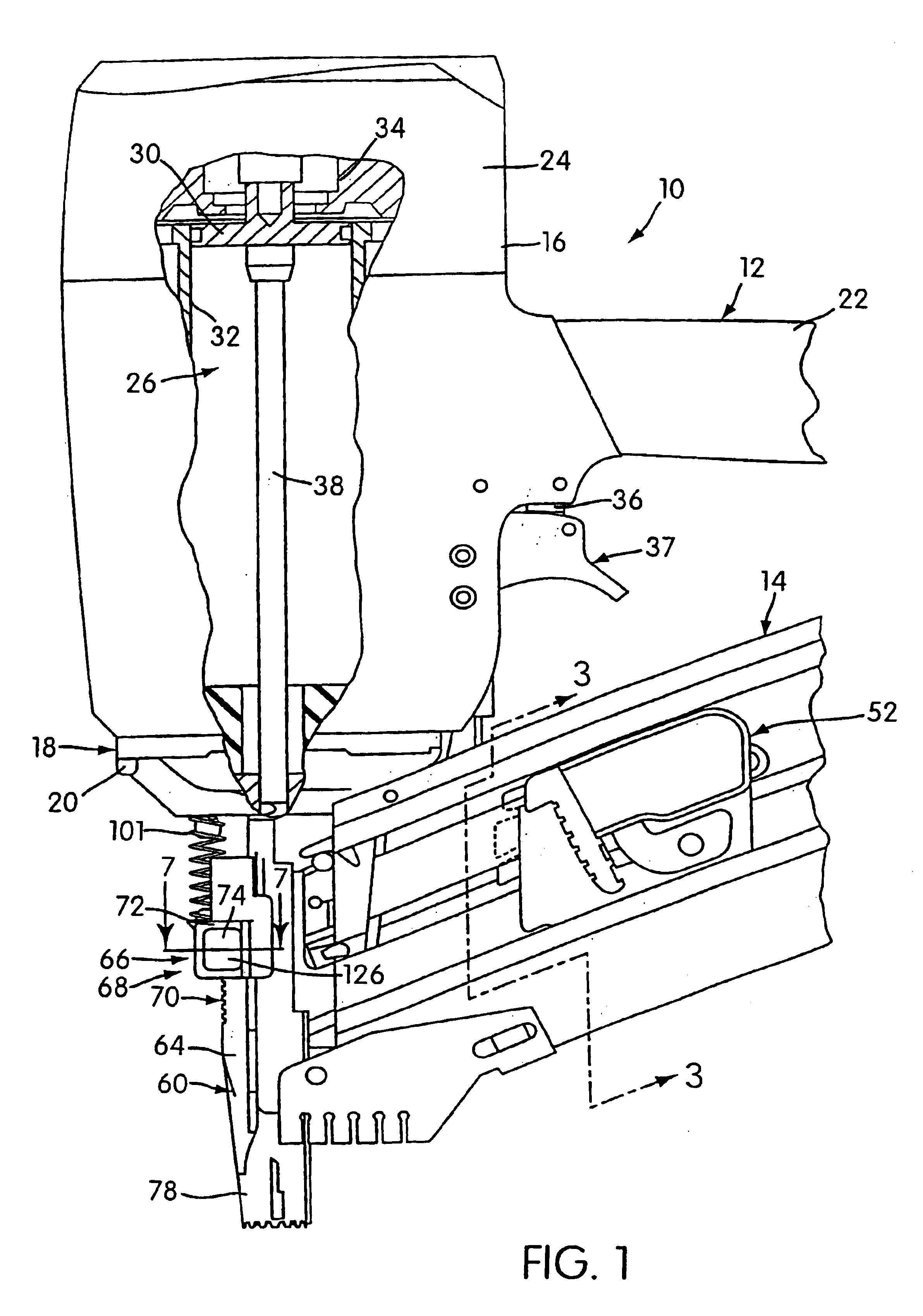
[0030]FIG. 1 shows a portable power operated fastener driving tool, generally designated 10, constructed according to the principles of the present invention. The fastener driving tool 10 includes a housing assembly 12 and a fastener magazine assembly 14. The housing assembly 12 includes a housing structure 16 which may be of conventional construction and a nosepiece assembly 18 secured thereto by conventional fasteners 20.

[0031]The housing structure 16 includes a hollow handle grip portion 22, the interior of which forms a reservoir for pressurized air supplied by a conventional pressurized air source (not shown) in communication therewith. The grip portion 22 is integrally formed with a vertically extending portion 24 of the housing structure 16 which contains a fastener driving mechanism 26 of conventional construction. A portion of the housing structure 16 has been broken away in FIG. 1 to show the construction of the fastener driving mechanism 26.

[0032]The fastener driving mech...


PUM

PropertyMeasurementUnit
Lengthaaaaaaaaaa
Forceaaaaaaaaaa
Depthaaaaaaaaaa

Abstract

A fastener driving tool includes a housing assembly with a nosepiece assembly defining a drive track. A driving mechanism is housed within the housing assembly to drive a fastener through the drive track and into a workpiece in response to a trigger. The tool includes a safety trip assembly which includes a trigger enabling portion and a workpiece engaging portion and is movable between an extended disabling position and a retracted enabling position. The safety trip assembly is biased toward the extended position and is moved toward the retracted position by engagement between the workpiece and the workpiece engaging member. The workpiece engaging portion is movable to permit adjustment of a length of the safety trip assembly. The safety trip assembly includes a coupling mechanism including a fixed locking structure formed on an exterior portion of the workpiece engaging portion and a manually operable locking mechanism. The locking mechanism is carried by the trigger enabling portion and includes a locking member mounting structure and has a manually operable locking member mounted thereon. The movable locking member is biased into a locking position, engaging the fixed locking structure and preventing relative movement between the workpiece engaging portion and the trigger enabling portion and may move into a releasing portion disengaging the fixed locking structure and permitting such relative movement. A user may manually move the locking mechanism against the bias by engaging the movable locking member and moving it from the locking position to the releasing position.

Description

[0001]This application claims benefit to provisional application Ser. No. 60 / 127,836 filed Apr. 5, 1999.BACKGROUND OF THE INVENTION[0002]Power operated fastener driving devices are in widespread use in the construction and building trades and typically include a power operated driving mechanism mounted within a housing that powers the driving movement of a drive element slidably mounted within a drive track that extends through a nose piece mounted to the housing. Typically when the driving mechanism is actuated, the drive element moves in a fastener driving direction through a drive stroke and then moves in the opposite direction through a return stroke during one cycle of operation. A trigger mechanism that is movable through an actuation stroke is commonly provided on the exterior of the housing to initiate an operating cycle.[0003]A magazine assembly mounted to the housing supplies a series of fasteners to the drive track through a lateral opening in the same and the leading fas...

Claims


Application Information

Patent Timeline
IPC IPC(8): B25C1/00B27F7/11B25C1/04B25C7/00
CPCB25C1/005B25C1/008
Inventor PERRA, ARTHUR E.
Owner STANLEY FASTENING SYST LP
Why Eureka
Try Eureka