Transfer of messages in a multiplexed system

a message and multiplexing technology, applied in the field of multiplexing system transmission, can solve the problems of compounding slot overhead, limiting the efficiency of the transport in the switch or in the performance of the reassembly function, and limiting the efficiency of the transport in the switch or in the reassembly function, so as to achieve the effect of limiting the overhead of the transpor

Inactive Publication Date: 2007-01-02
QPSX COMM
View PDF21 Cites 66 Cited by
  • Summary
  • Abstract
  • Description
  • Claims
  • Application Information

AI Technical Summary

Problems solved by technology

However, these are limited either in the efficiency of the transport in the switch or in the performance of the reassembly function.
The efficiency of the transport is typically limited by the overheads that are carried on each slot.
The problem with the slot overhead is compounded by addressing requirements.
This approach to segmentation is clearly inefficient with small (less than 32 bytes) slot sizes.
The limitation with this approach is that the number of slots between consecutive segments of the message is limited by the maximum value of the count field.
Also, in the case of a multiple access switch, the source cannot transmit more than one message at a time.
This reduces the efficiency of transfer when connection oriented reassembly schemes are used.

Method used


Image

  • Transfer of messages in a multiplexed system
  • Transfer of messages in a multiplexed system
  • Transfer of messages in a multiplexed system

Examples


Embodiment Construction

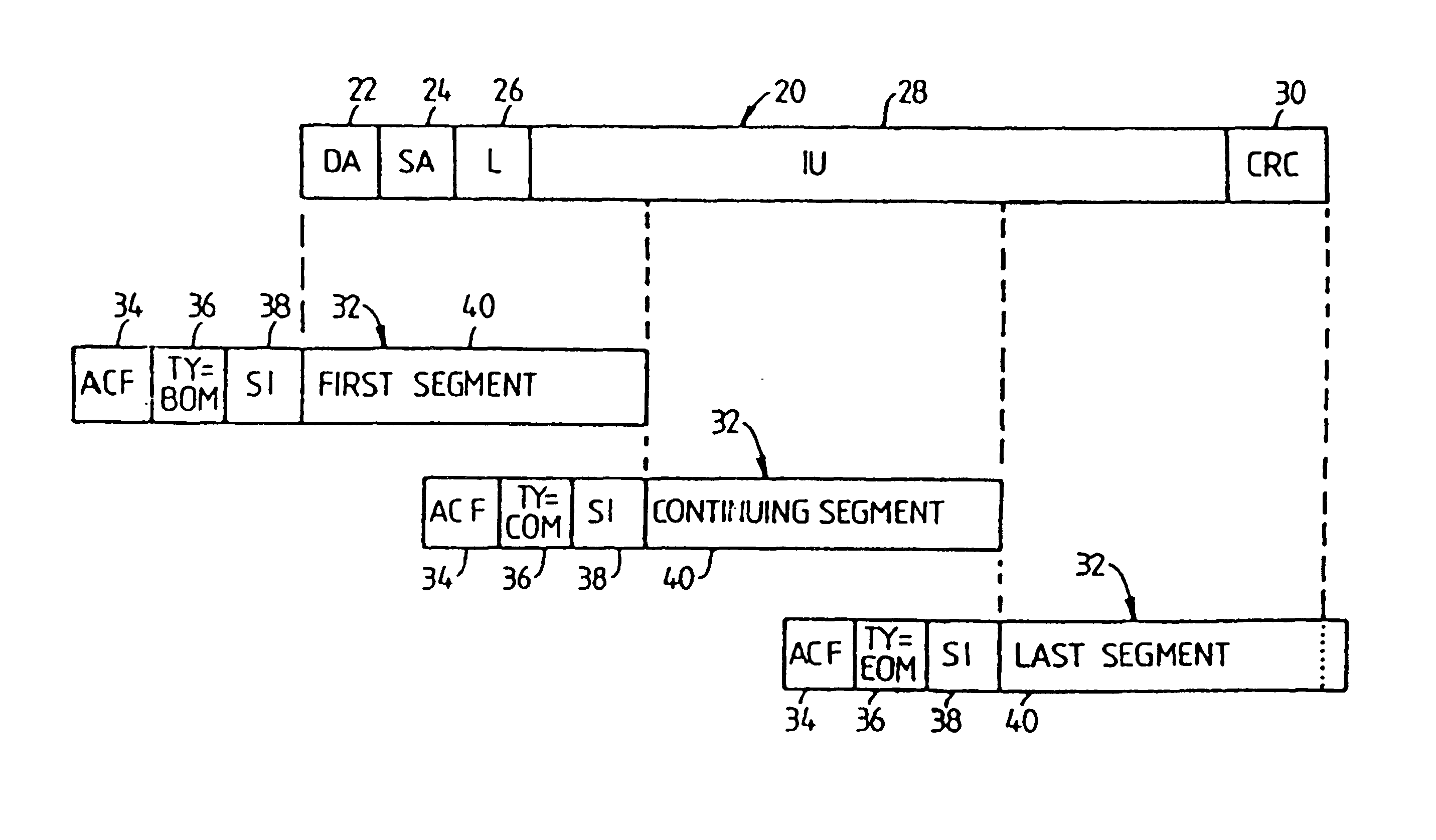
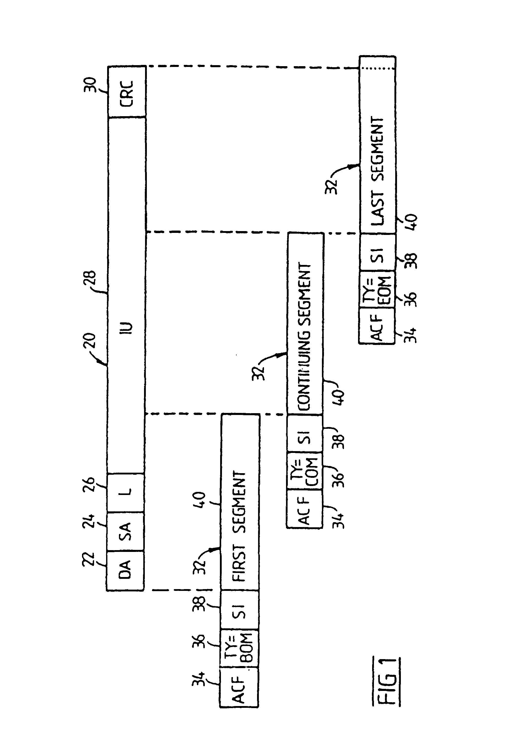
[0033]FIG. 1 diagrammatically shows a message 20 which is of variable length. The message includes address fields 22 and 24 for the destination address (DA) and source address (SA). The message includes a length field (L) 26 and an information field (IU) 28 followed by an error checking field (CRC) 30. The error checking field 30 can be of any known type.

[0034]In accordance with the invention, the variable length message 20 is segmented into a number of slots 32 of equal length. The method places the address field 22 and 24 in the first of the slots 32 and subsequently logically associates the following slots of the message with the first slot using a unique identifier, as is diagrammatically illustrated in FIG. 1.

[0035]Each slot 32 has an Access Control Field (ACF) 34. TYPE field 36 and Source Identifier (SI) field 38. In accordance with the invention, the SI field 38 is used to provide the logical linking between slots 32 of the same message. The slots 32 also include an informati...


PUM


Abstract

A method and apparatus for transmitting variable length messages on a network in fixed length slots including the provision of a source identifier field in the header of each slot, the source identifier field including a code which is uniquely associated with the message to be transmitted. The fixed length slots are then transmitted on the network and reassembly of the slots by a reassembly machine is controlled in accordance with the identifier codes in the slot.

Description

[0001]This is a reissue divisional (and claims the benefit of priority under 35 USC 120) of U.S. Application Ser. No. 08 / 122,934, filed Sep. 17, 1993, which is an application for reissue of U.S. Pat. No. 5,050,166(now U.S. Pat. No. RE37,494, issued Jan. 1, 2002) claiming the priority date of U.S. Pat. No. 5,050,166. The disclosure of the prior application is considered part of (and is incorporated by reference into) the disclosure of this application.<?insert-end id="INS-S-00001" ?>[0002]This application claims (under 35 USC §119) the benefit of patent application serial number P10884, filed in Australia on Mar. 17, 1987.<?insert-end id="INS-S-00002" ?>[0003]Notice: More than one reissue application has been filed for the reissue of U.S. Pat. No. 5,050,166 which issued on Sep. 17, 1991.[0004]These include:[0005]1. Ser. No. 08 / 122,934, filed Sep. 17, 1993, now U.S. Pat. No. RE37,494, reissued on Jan. 1, 2002; [0006]2. Ser. No. 09 / 919,725, filed on Jul. 31, 2001, which is ...

Claims


Application Information

Patent Timeline
Patent Type & Authority Patents(United States)
IPC IPC(8): H04J3/24H04L12/54H04Q11/04H04J3/16H04L5/22H04L12/64H04L12/70H04L12/801H04L12/931H04L29/06H04L29/08
CPCH04J3/16H04L47/34H04L49/606H04L2012/565H04L2012/5652H04L2012/641H04L69/324H04L9/40H04L47/43H04L47/10
Inventor CANTONI, ANTONIONEWMAN, ROBERT M.
Owner QPSX COMM
Why Eureka
Try Eureka