Flashlights and other battery-powered apparatus for holding and energizing transducers

a battery-powered, electric transducer technology, applied in the direction of lighting and heating apparatus, cell components, cell component details, etc., can solve the problems of deteriorating performance of prior-art flashlights, difficult to retain a well-focused light output when a light source is replaced,

Inactive Publication Date: 2008-01-22
SUREFIRE LLC
View PDF139 Cites 29 Cited by
  • Summary
  • Abstract
  • Description
  • Claims
  • Application Information

AI Technical Summary

Benefits of technology

[0009]It is an object of one of the inventions herein disclosed and claimed to provide improved rechargeable battery-powered apparatus for holding and energizing at least one electric transducer, wherein any transducer is isolated from battery chargers and charging currents, whereby transducers are protected and charging current limitations imposed by transducers are avoided, and wherein battery charging currents are led through parts of the apparatus without the need of any electrodes, wires and the like that would have to be electrically insulated from the apparatus part through which the particular electrode or wire proceeds.

Problems solved by technology

Prior-art apparatus with rechargeable batteries for powering one or more electric light sources or other transducers either exposed transducers to battery charging currents, especially if the user accidentally turned on a transducer energizing switch, or imposed charging current limitations by charging the batteries through a flashlight filament or other active electric transducer part, or required the provision of special isolated electrodes, wires and the like for feeding battery charging currents through apparatus parts, or exposed battery chargers to shorting through faulty positioning of switches on the apparatus, or had two or more of such drawbacks.
With prior-art flashlights, it is often difficult to retain a well-focused light output when a light source is replaced.
Also prior-art flashlights often are impaired by a deteriorating performance because of progressively corroding switch contacts and battery terminal contacts.

Method used


Image

  • Flashlights and other battery-powered apparatus for holding and energizing transducers
  • Flashlights and other battery-powered apparatus for holding and energizing transducers
  • Flashlights and other battery-powered apparatus for holding and energizing transducers

Examples


Embodiment Construction

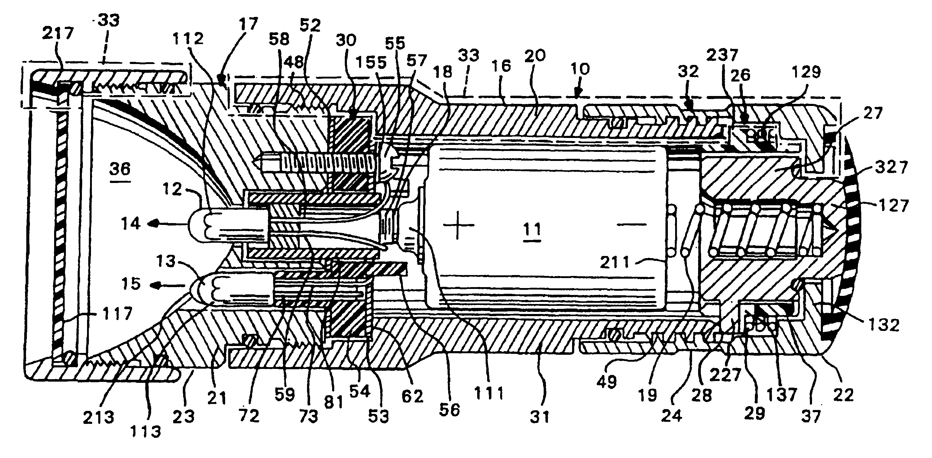
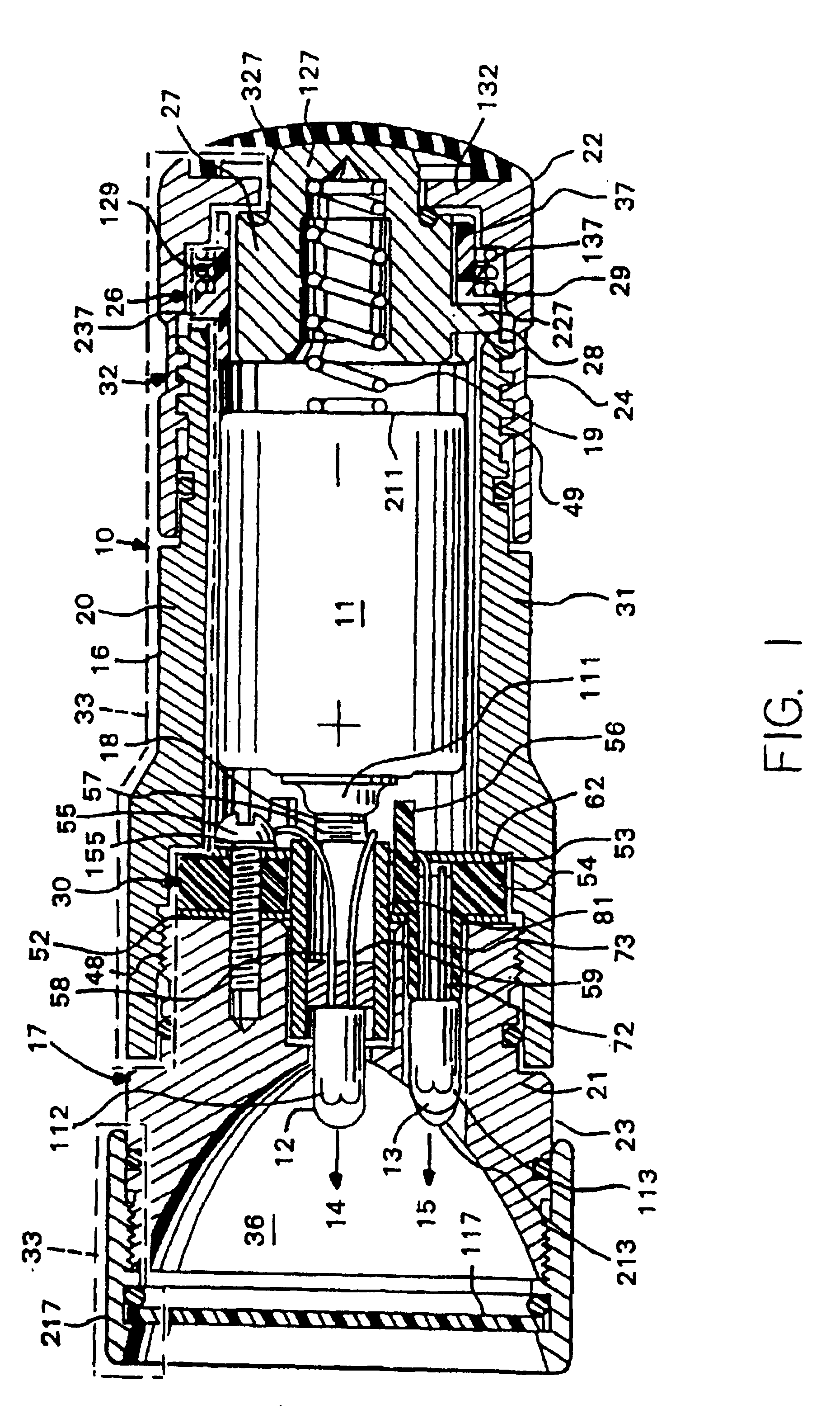
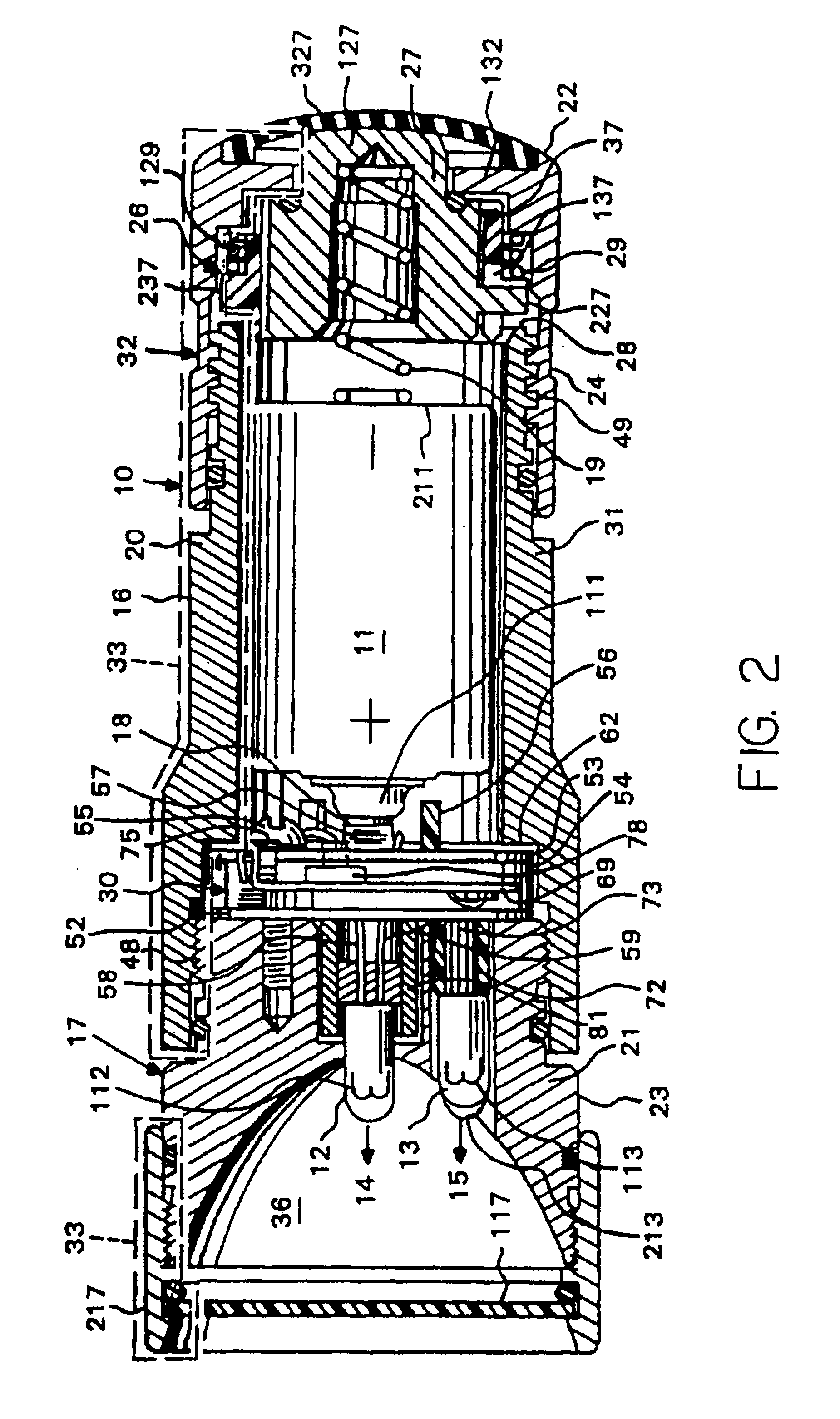
[0030]The drawings show battery-powered apparatus 10 for holding and energizing an electric transducer producing an output from a battery current. One or more batteries 11 may be held in the battery housing. Apparatus within the scope of the invention include flashlights, laser pointers, electrically powered tools, and other devices. Accordingly, the transducer may include one or more light bulbs 12 and / or 13, laser diodes or other battery energized light sources, electric screw drivers or other torque converters, or other electric actuated tools or devices. The output correspondingly may be a high or low beam or other light output 14 and / or 15, or a torque or other physical quantity, but no limitation in this respect is intended hereby.

[0031]The apparatus 10 has a hand-held battery housing 16 carrying a transducer mount 17. A first internal battery terminal contact 18 is located at the transducer mount. A second internal battery terminal contact 19 is remote from the transducer mou...


PUM

PropertyMeasurementUnit
current-aaaaaaaaaa
electrically conductiveaaaaaaaaaa
electricaaaaaaaaaa

Abstract

A battery-powered apparatus for holding and energizing an electric transducer, includes a hand-held battery housing carrying the transducer mount, and first and second internal battery contacts. A first external battery charge terminal is on the transducer mount, and a second external battery charge terminal is on a part of the battery housing, such as its end cap. A double-throw switch has a common element electrically connected to an internal battery terminal contact, has a first switched contact leading to a first terminal of the electric transducer, and has opposite second switched contact electrically connected to an external battery charge terminal. If there are two electric transducers, they may be a part of a light source comprising a reflector, a first electric lamp having a filament at its focal point, and a second electric lamp extending into that reflector beside the first electric lamp.

Description

TECHNICAL FIELD[0001]The subject inventions relate to flashlights and other battery-powered apparatus for holding and energizing electric transducers.BACKGROUND[0002]Battery-Powered apparatus for holding and energizing one or more electric transducers are well known and include flashlights, laser pointers, and electrically powered tools, to name a few examples.[0003]Prior-art apparatus with rechargeable batteries for powering one or more electric light sources or other transducers either exposed transducers to battery charging currents, especially if the user accidentally turned on a transducer energizing switch, or imposed charging current limitations by charging the batteries through a flashlight filament or other active electric transducer part, or required the provision of special isolated electrodes, wires and the like for feeding battery charging currents through apparatus parts, or exposed battery chargers to shorting through faulty positioning of switches on the apparatus, o...

Claims


Application Information

Patent Timeline
Patent Type & Authority Patents(United States)
IPC IPC(8): H01M2/10F21L4/02H01H9/20H01M50/202H01M50/204H01M50/224H01M50/231H01M50/271H01M50/296
CPCF21L4/02H01M2/10H01H9/20Y02E60/10H01M50/204H01M50/224H01M50/231H01M50/202H01M50/296H01M50/271
Inventor MATTHEWS, JOHN WALLACE
Owner SUREFIRE LLC
Why Eureka
Try Eureka