Power supply system

a power supply system and power supply technology, applied in secondary cell servicing/maintenance, emergency power supply arrangements, safety/protection circuits, etc., can solve the problems of power supply system that cannot supply uninterrupted power, limit downsizing, etc., to prevent a lithium ion battery capacity drop, eliminate the need for connection switching or disconnecting the lithium ion battery, and constant connection

Inactive Publication Date: 2007-05-10
NTT FACILITIES INC
View PDF8 Cites 36 Cited by
  • Summary
  • Abstract
  • Description
  • Claims
  • Application Information

AI Technical Summary

Benefits of technology

[0009] In view of the aforementioned circumstances, the present invention has as its object to provide a power supply system that can protect a battery from overcharging or prevent a drop in capacity of a lithium ion battery and realizes a constant connection to eliminate the need for connection switching or disconnecting of the lithium ion battery. It is another object of the present invention to provide a power supply system that prevents variations in the cell voltage of each lithium ion battery during charging.

Problems solved by technology

However, when using valve-regulated lead-acid batteries, there have been limits to downsizing due to restrictions imposed on the current value during high-current discharge.
This has as a result led to restrictions on downsizing the power supply system as well.
Therefore, a power supply system that supplies uninterrupted power could not be achieved.
However, a power supply system adopting such measures has not been conventionally achieved.

Method used


Image

  • Power supply system
  • Power supply system
  • Power supply system

Examples


embodiment 1

(Embodiment 1)

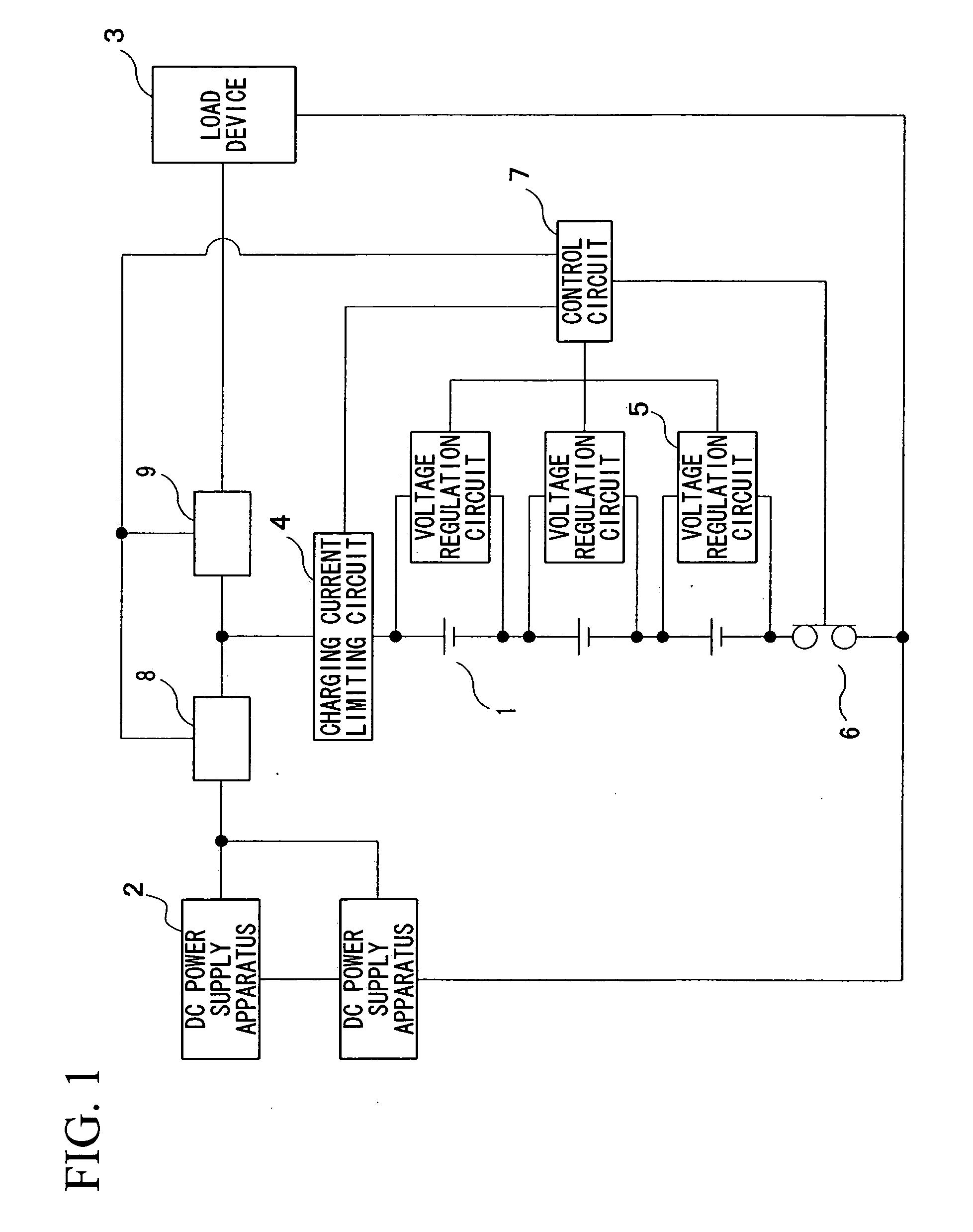
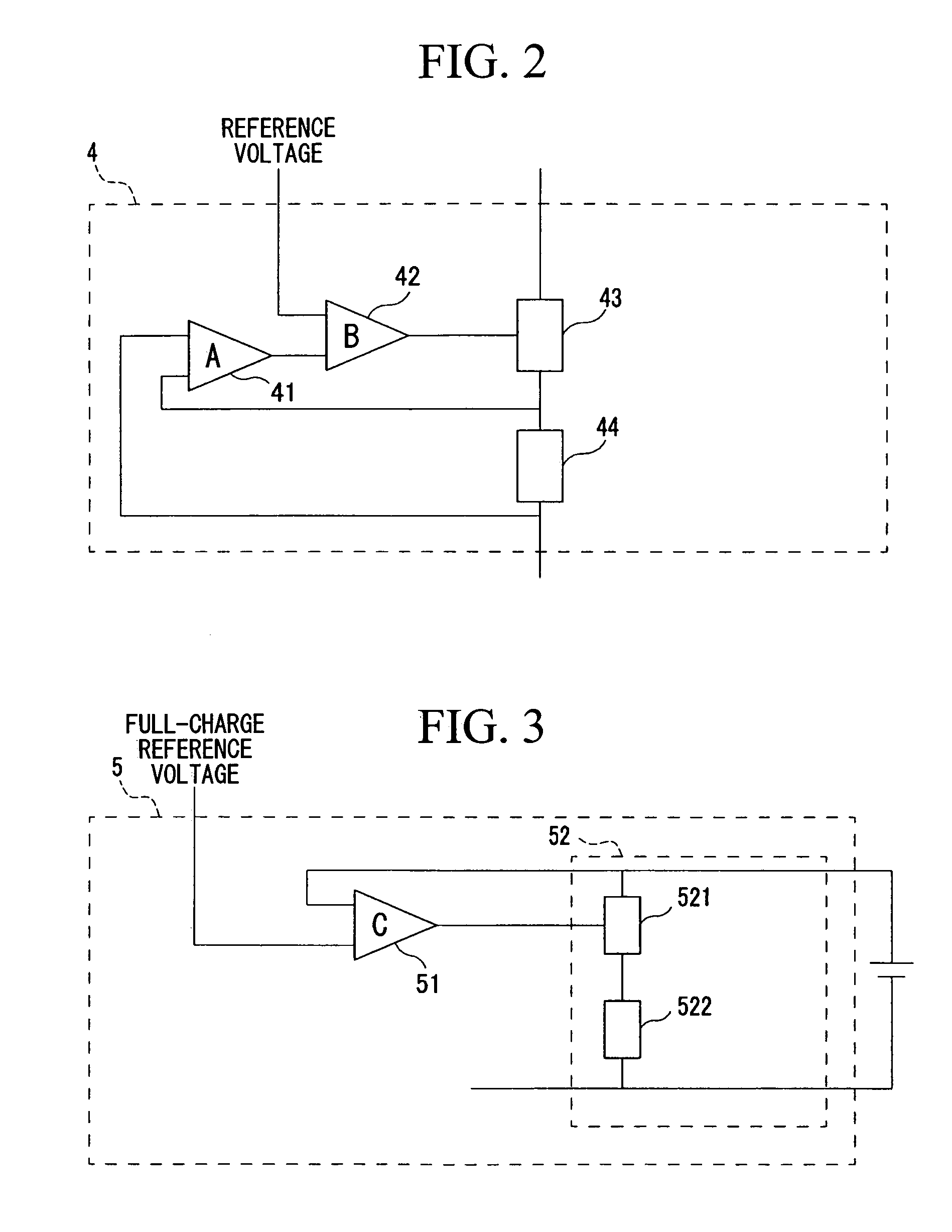
[0058]FIG. 7 shows the embodiment of the charging current limiting circuit 4. A resistor R100 is used for the charging current detecting element 44, and an FET Q100 is used for the charging current control element 43. A plurality of the FETs Q100 are used in parallel connection in accordance with the loss. Also, during discharge the FET Q100 forms a discharge path by being turned completely ON, or the FET Q100 forms a discharging path by being turned OFF and using the parasitic diode D100 of the FET Q100.

[0059] Specifically, the charging current detected by the resistor R100 is input to the differential amplifier constituted by resistors R1 to R4 and the error amplifier A 41, where it is amplified to a value determined in advance. The output thereof is then input to the inverted input terminal of the error amplifier B 42 through a resistor R7. The reference voltage that sets the charging current is divided by the resistors R5 and R6 from the control circuit 7 and inpu...

embodiment 2

(Embodiment 2)

[0060]FIG. 8 shows the embodiment of the voltage regulation circuit 5. In the charging current bypass circuit 52 of the voltage regulation circuit 5, a resistor R200 is used for the bypass current limiting element 522, and an FET Q200 is used for the bypass current control element 521.

[0061] Here, the voltage of the lithium ion battery 1 is detected and input to the inverted input of the error amplifier C 51 via a resistor R15, and the reference voltage from the control circuit 7 is input to the non-inverted input terminal of the error amplifier C 51 via resistors R13 and R14 and a condenser C3. Here, the error amplifier C 51 outputs an output signal so that the two inputs become the same value. The output signal is input to the base of a transistor Q2 via a resistor R18.

[0062] The transistor Q2 provides a signal to the gate of the bypass current control element Q200 via a resistor R19 to control the bypassed current, performing control so that the voltage of the lit...


PUM

PropertyMeasurementUnit
voltageaaaaaaaaaa
voltageaaaaaaaaaa
voltageaaaaaaaaaa

Abstract

A power supply system comprising: a DC power supply apparatus; a load device; a lithium ion battery for backup that is connected in parallel with said DC power supply apparatus and said load device; a charging current limiting circuit that is connected in series with said lithium ion battery and supplies a charging current of an arbitrary value independent of load fluctuations in the charging path of the lithium ion battery; a switch that disconnects said lithium ion battery from said DC power supply apparatus or said load device, or connects said lithium ion battery to said DC power supply apparatus or said load device; and a control circuit that monitors the voltage value of said charging path, sets a reference voltage setting used for setting the charging current of an arbitrary value in said charging current limiting circuit, and controls said switch when said voltage of said charging path exceeds a specified voltage value during charging.

Description

TECHNICAL FIELD [0001] The present invention relates to a power supply system having a constitution in which a lithium ion battery for backup is connected in parallel to a DC power supply apparatus and a load device. [0002] Priority is claimed on Japanese Patent Application No. 2003-397489, filed Nov. 27, 2003, the content of which is incorporated herein by reference. BACKGROUND ART [0003] A valve-regulated lead-acid battery is mainly used for backup in a power supply system that supplies electrical power to a load device such as a communication device. Valve-regulated lead-acid batteries have come to be widely used in communication devices because of their low cost and the benefits they bring in terms of system configuration. Such benefits include performing maintenance charging required for capacity preservation and recovery charging after a power outage by maintaining a constant voltage. [0004] In recent years, there has been an increasing demand for downsizing of power supply sy...

Claims


Application Information

Patent Timeline
Patent Type & Authority Applications(United States)
IPC IPC(8): H02J7/00H02J7/34H01M10/44H02J7/02H02J7/04H02J9/06
CPCH02J7/045H02J9/061H02J2007/0039H02J7/00304H02J7/04H02J7/00302H02J7/007182H02J7/00306H02J7/34
Inventor TAKAGI, SHINYAMUROOKA, KIYOSHINEMOTO, KEN-ICHI
Owner NTT FACILITIES INC
Why Eureka
Try Eureka