Rotary hammer

a rotary hammer and hammer head technology, applied in the field of rotary hammer, can solve the problems of difficult assembly, relatively high manufacturing cost, and relatively complex mechanism of this type, and achieve the effect of simple and reliable mod

Inactive Publication Date: 2009-02-24
BLACK & DECKER INC
View PDF19 Cites 11 Cited by
  • Summary
  • Abstract
  • Description
  • Claims
  • Application Information

AI Technical Summary

Benefits of technology

[0009]Therefore, it is an object of this invention to provide a rotary hammer having a simple and reliable mode ch

Problems solved by technology

However, mechanisms of this type tend to be relatively complex, use parts which are intricate and/or difficult to manufacture inexpensively in bulk, with sturdy qualities that can withstand sustained use of the hammer, and/or are relatively difficult to assemble.
Such parts are relatively expensive to manufacture in such a way that the par

Method used


Image

  • Rotary hammer
  • Rotary hammer
  • Rotary hammer

Examples


Embodiment Construction

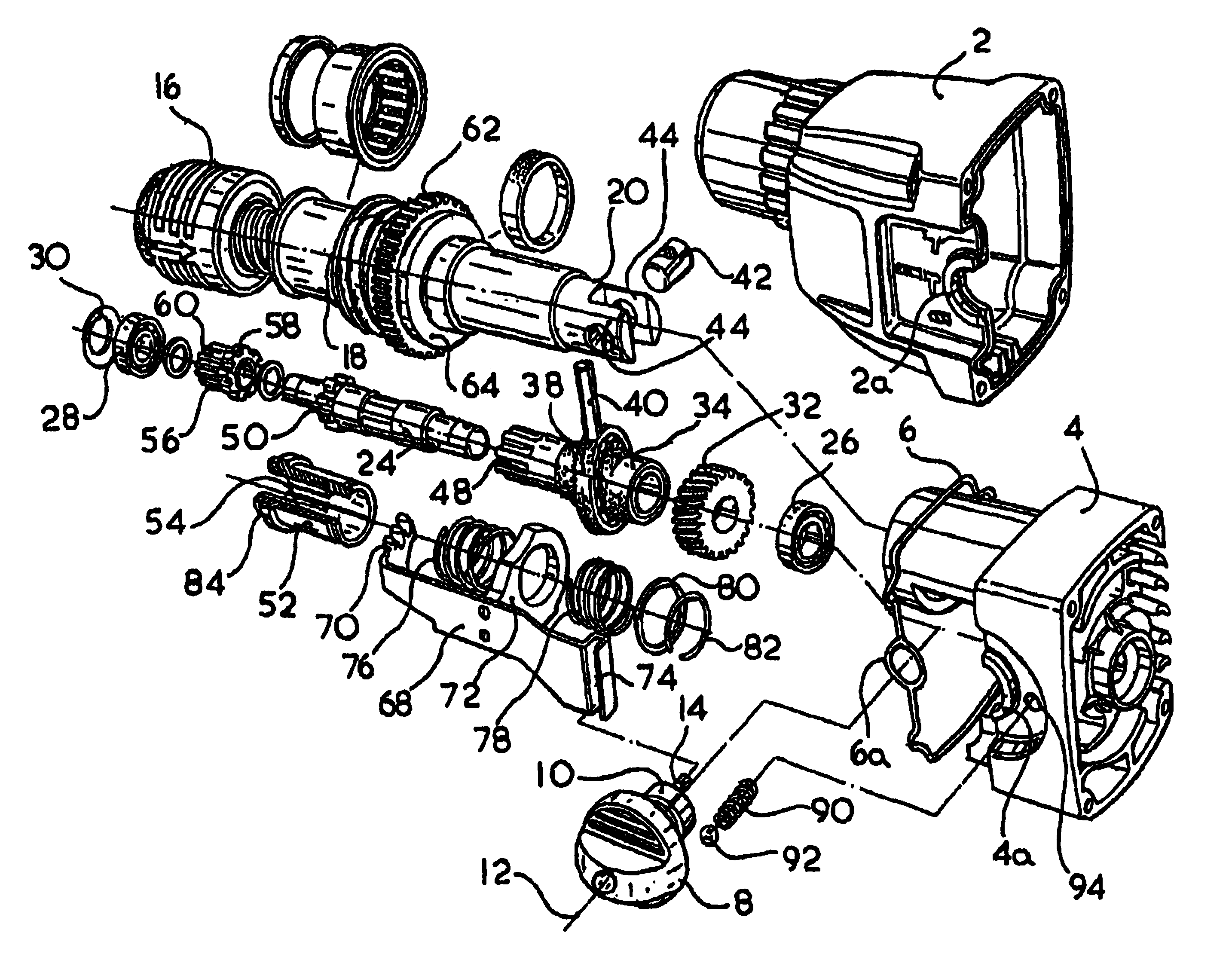
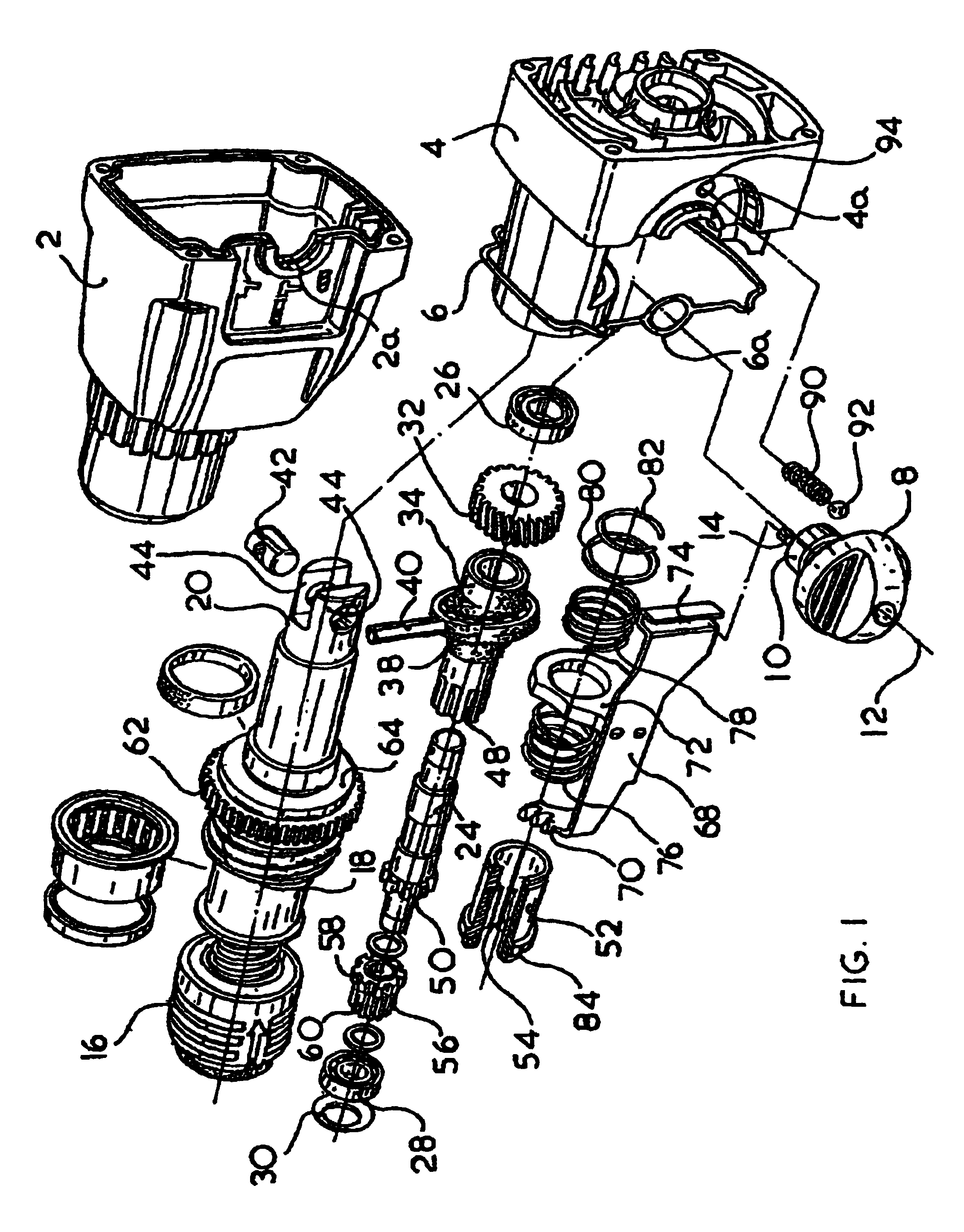
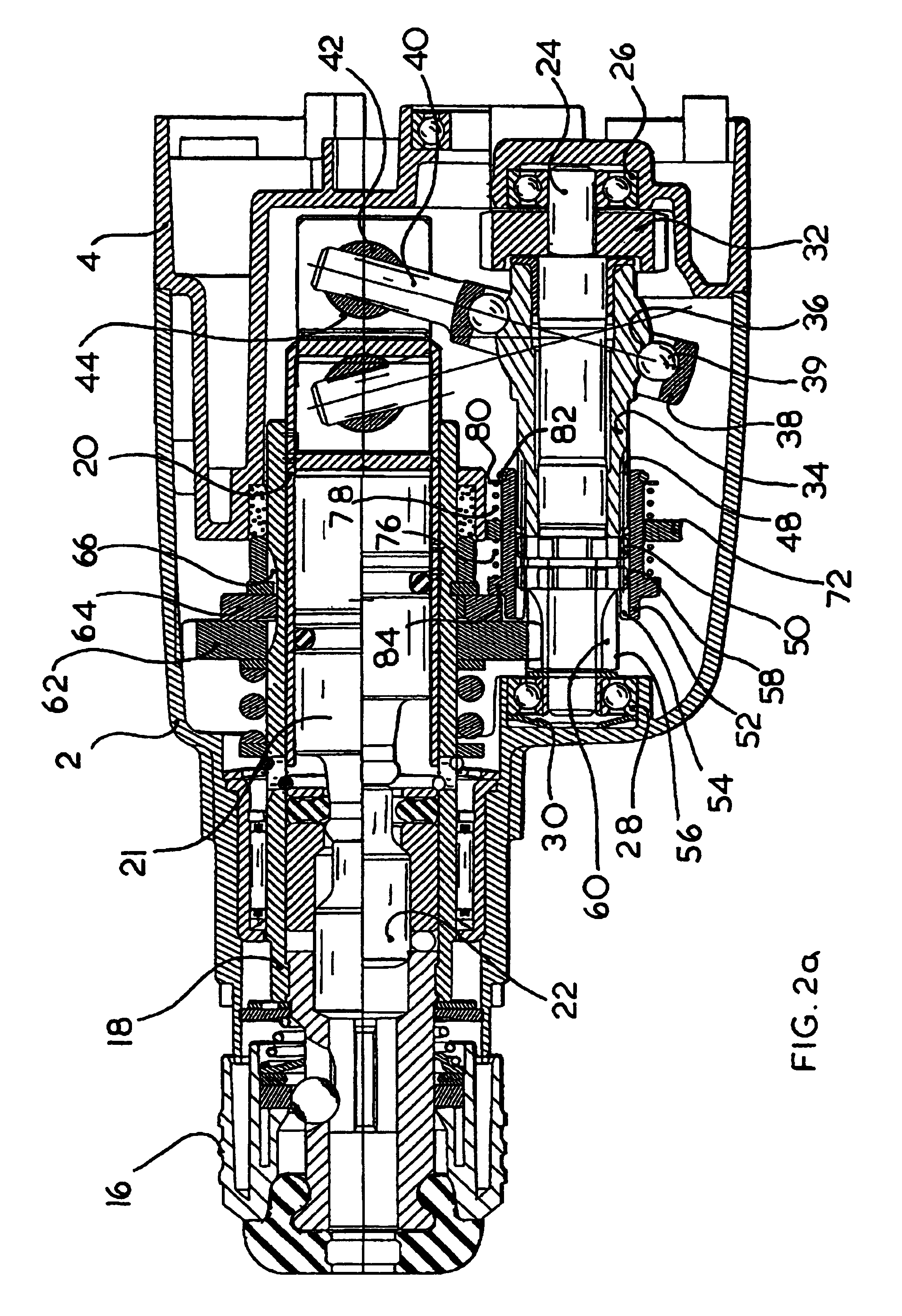
[0036]Referring to FIGS. 1, 2a, 2b and 2c, a first embodiment of a rotary hammer includes a forward housing part 2 and a central housing part 4, which are held together by threaded fasteners (not shown) to form a housing for a hammer spindle, a spindle drive arrangement, a hammer drive arrangement and a mode change mechanism. A resilient housing seal 6 fits between the housing parts 2 and 4 in a complementary recess provided in co-operating end surfaces of the housing parts to form a seal between the housing parts. The housing parts 2 and 4 are each formed with semi-circular recesses 2a and 4a, respectively, which co-operate to form a circular recess, lined with a ring section 6a of the housing seal 6, within which a mode change knob 8 is mounted for rotation about a mode change axis 12. The mode change knob 8 has an axle with an enlarged portion 10 which is captured within the hammer housing when the housing parts 2 and 4 are assembled together. In this manner, the mode change knob...


PUM

PropertyMeasurementUnit
Selectivityaaaaaaaaaa

Abstract

A rotary hammer includes a spindle 18 which can be rotatably driven by an intermediate shaft 24 by way of a drive device. A tool holder 16 is arranged for rotation with the spindle 18, and for releasably holding a bit or tool for selective rotation and/or reciprocation. A pneumatic hammering arrangement facilitates repeated impacting of the bit or tool for reciprocation within the tool holder (16). A mode change mechanism includes a knob 18 for selectively operating the rotary hammer in any of three modes, identified as a rotary drive only mode, a hammer only mode and a rotary hammer mode.

Description

CROSS-REFERENCE TO RELATED APPLICATION [0001]This application is a Reissue of U.S. Pat. No. 6,666,284 B2, issued Dec. 23, 2003, which claims priority to Great Britain application Serial No. 0008465, filed Apr. 17, 2000. <?insert-end id="INS-S-00001" ?>BACKGROUND OF THE INVENTION[0002]This invention relates to a rotary hammer, and particularly relates to a rotary hammer with a mode change mechanism for switching the rotary hammer for operation in any one of a hammer only mode, a rotary drive only mode and a rotary hammering mode.[0003]In a hammer only mode of a conventional rotary hammer, a bit is inserted into a tool holder of the hammer and is repeatedly struck by a hammering mechanism and is not rotatably driven. In a rotary drive only mode, the bit is rotatably driven and is not subject to impacts from the hammering mechanism. In a rotary hammering mode, the bit is repeatedly struck by the hammering mechanism and is simultaneously rotatably driven.[0004]Conventional rotary ...

Claims


Application Information

Patent Timeline
IPC IPC(8): B25D11/00B23B45/16B25D16/00
CPCB25D16/00B25D16/006B25D2211/061
Inventor STIRM, MICHAEL
Owner BLACK & DECKER INC
Why Eureka
Try Eureka