
Signalling method

a signalling and data technology, applied in the field of signalling data transmission methods, can solve the problems of delay of time critical rrc messages, no means to treat these entities separately, and no mechanism for prioritizing more recent messages

Inactive Publication Date: 2010-09-28
QUALCOMM INC
View PDF20 Cites 12 Cited by
  • Summary
  • Abstract
  • Description
  • Claims
  • Application Information

AI Technical Summary

Benefits of technology

[0010]An object of the invention is to realize a signalling method, which alleviates the aforementioned problems of prior art. A further object of the invention is to provide a method for transmission of control signalling, which allows determining of quality of service levels for different signalling traffic streams.
[0011]A still further object of the invention is to provide the aforementioned objects of the invention, without adding complexity in the protocol layers above the RRC protocol layer.
[0017]The inventive method provides integrity protection of MM and higher layer messages as a consequence of the transmission of the messages in RRC DIRECT TRANSFER messages. The inventive method allows controlling of priority between MM and higher layer messages and RRC messages in the radio interface by adjusting the QoS parameters of bearers used to transfer the messages.

Problems solved by technology

However, there is currently no means to treat these entities separately for example for setup, reconfiguration or release.
The problems with the prior art solution used at the time of writing this patent application are mainly related to priority control of signalling traffic.
A problem can arise for example in a case, when a very long higher layer message is passed to RLC layer which buffers the message, and when a time critical RRC message also needs to be sent.
In this situation, the RLC layer transmits the buffered messages first before transmitting more recent messages, which results in a delay of the time critical RRC message.
Currently there are no mechanisms allowing priorization of more recent messages over those messages waiting in RLC transmission buffer.
This solution creates some problems related to integrity control function—which is defined as a RRC layer function—and to the existing procedures in Iu interface.
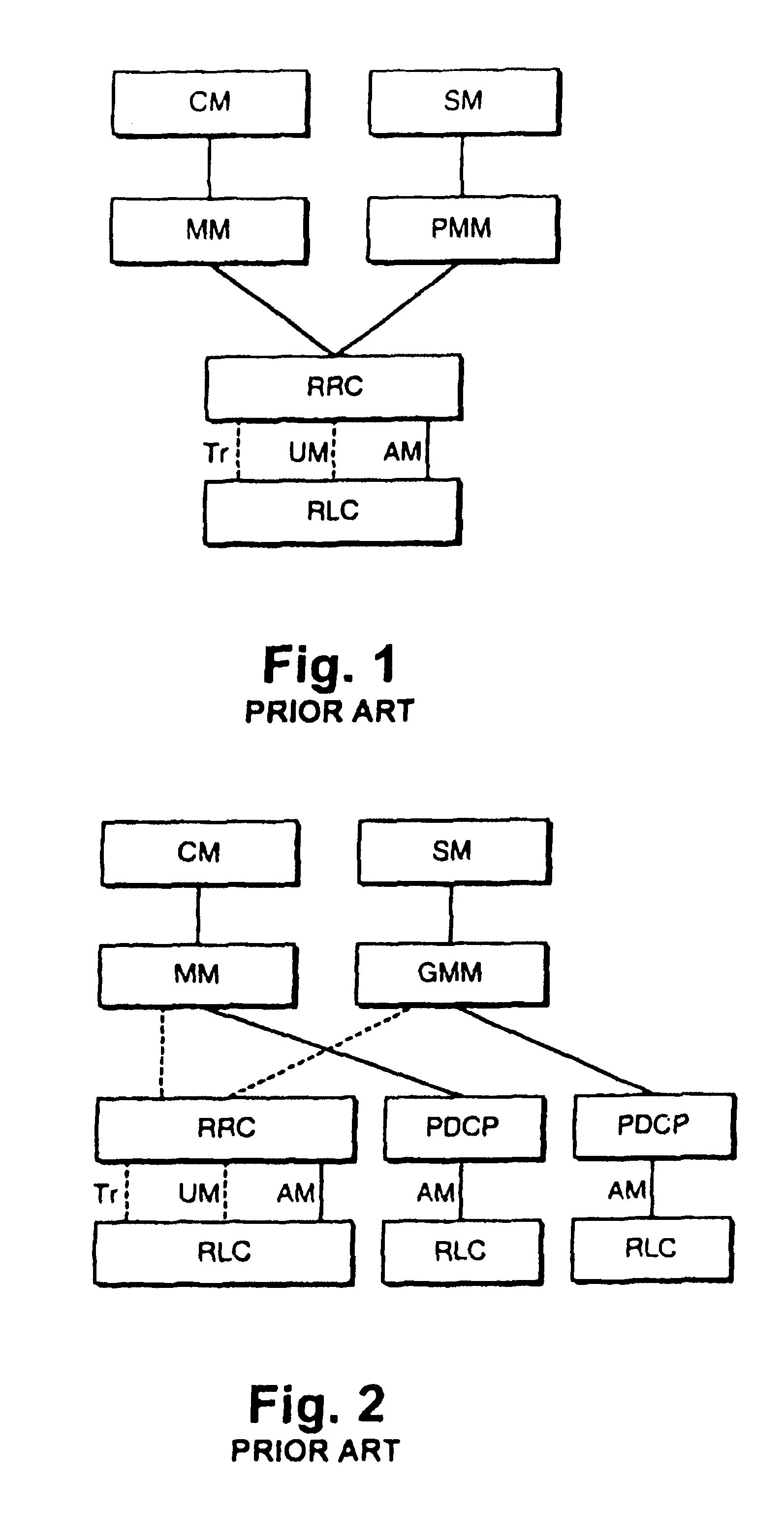
For example, the proposed solution increases the complexity of the MM and PMM protocol implementations, since primitive interfaces arc needed not only for the RRC protocol, but for the PDCP protocol as well.
This would add complexity to the implementations of the PDCP protocol.
As a consequence, the complexity of PDCP protocol increases and an additional header field is needed in PDCP data payload data units (PDU), since the integrity function requires a counter value to be transmitted with each piece of integrity protected data for use by the integrity protection algorithm.

Method used


Image

  • Signalling method
  • Signalling method
  • Signalling method

Examples


Embodiment Construction

A. A First Group of Advantageous Embodiments of the Invention

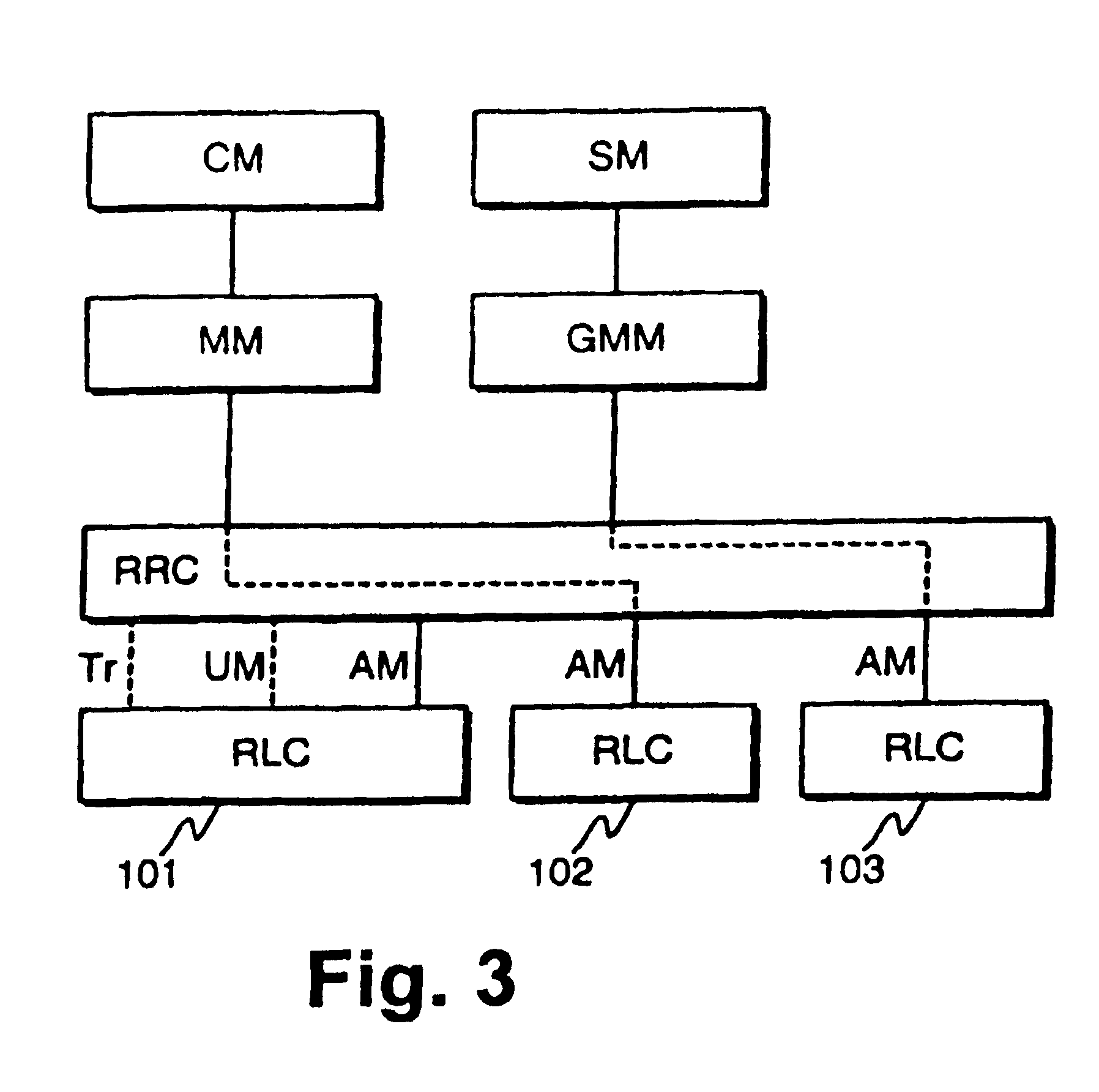
[0026]FIG. 3 illustrates protocol stack configuration for signalling transfer according to an advantageous embodiment of the invention. This figure illustrates the example case that a separate radio bearer is reserved for each CN domain. In FIG. 3, each radio bearer is represented by a RLC entity corresponding to the radio bearer. FIG. 3 illustrates, that signalling from the circuit switched CN domain (CM, MM) is transmitted via a second RLC entity 102, while signalling from the packet switched CN domain (SM, PMM) is transmitted via a third RLC entity 103, while a first RLC entity is used for transmission of the rest of RRC messages.

[0027]According to the invention, the RRC protocol can use one or more signalling radio bearers (SRB) i.e. RLC entities for transmission of signalling traffic between the network and the mobile communication means, i.e. UE (user equipment). In other words, the signalling link between a UE and a...


PUM


Abstract

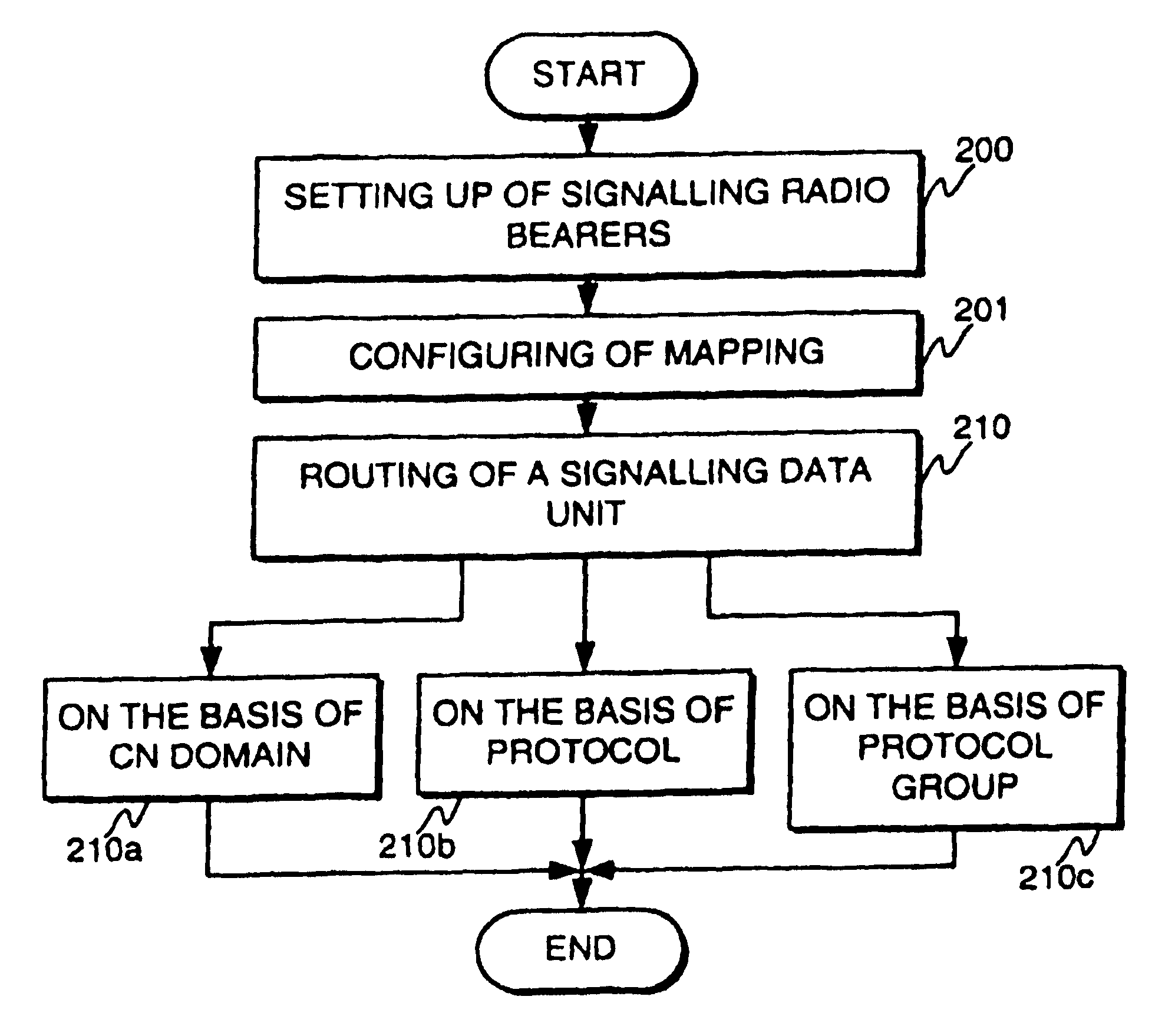
The invention relates to methods for transmission of signalling data in cellular telecommunication networks. According to the invention, multiple radio bearers can be allocated for transferring signalling traffic, but all higher layer signalling is in any case taken through the RRC protocol. In the inventive method, MM and higher layer messages are sent using RRC DIRECT TRANSFER messages, but a separate RLC entity is set up for RRC DIRECT TRANSFER messages. In various embodiments of the invention, separate radio bearers can be set up for individual CN domains and / or upper layer protocols and / or for a group of RRC messages.

Description

BACKGROUND OF THE INVENTION[0001]1. Field of the Invention[0002]The invention relates to methods for transmission of signalling data in cellular telecommunication networks. Especially, the invention is related to such a method as specified in the preamble of the independent method claim.[0003]2. Description of Related Art[0004]The current concept of a signalling radio bearer in the UMTS system (universal mobile telecommunication system) defines that there is only one radio bearer for signalling traffic between the cellular network and a mobile communication means. Both the RRC (radio resource control) and higher protocol layers use the same radio bearer, i.e. the same RLC (radio link control) entity. In some implementations it is possible to have two RLC entities for signalling traffic, one entity for unacknowledged mode transfer and one entity for acknowledged mode transfer. However, there is currently no means to treat these entities separately for example for setup, reconfigurati...

Claims


Application Information

Patent Timeline
IPC IPC(8): H04L12/28H04L12/56H04L29/06H04W72/12
CPCH04W28/065H04W76/12H04W72/20
Inventor AHMAVAARA, KALLEVIALEN, JUKKA
Owner QUALCOMM INC
Learn More