Rod introduction apparatus

Inactive Publication Date: 2012-07-17
WARSAW ORTHOPEDIC INC
View PDF54 Cites 23 Cited by
  • Summary
  • Abstract
  • Description
  • Claims
  • Application Information

AI Technical Summary

Benefits of technology

[0026]Still a further object of the present invention is to provide a multiple action insertion apparatus that is capable of gripping an implant, approximating the implant and an laterally offset longitudinal member, and reducing the vertical distance between the implant and the longitudinal member.
[0027]Another object of the presen

Problems solved by technology

In some cases, the threaded post of a bolt type bone anchor is not long enough to extend through a connector attached to the rod.
One problem with this arrangement is that the fork tines must pass between the implant and the bone, which in many cases may be difficult and may result in damage to the bone.
Moreover, the connection between the fork tines and the implant is not a secure engagement and may result in the rod introducer slipping during the procedure of forcing the rod into the implant.
This unnecessarily creates a complication for the surgeon, i.e. maintaining both the reduction mechanism and the hook in the desired position while attempting to thread the rod through various implants and the opening in the reduction apparatus.
Moreover, once the rod has been reduced into the implant opening, the reduction apparatus interferes with visualizing the implant and rod connecti

Method used


Image

  • Rod introduction apparatus
  • Rod introduction apparatus
  • Rod introduction apparatus

Examples


Embodiment Construction

[0049]For the purposes of promoting an understanding of the principles of the invention, reference will now be made to the embodiments illustrated in the drawings and specific language will be used to describe the same. It will nevertheless be understood that no limitation of the scope of the invention is thereby intended, such alterations and further modifications in the illustrated device, and such further applications of the principles of the invention as illustrated therein being contemplated as would normally occur to one skilled in the art to which the invention relates.

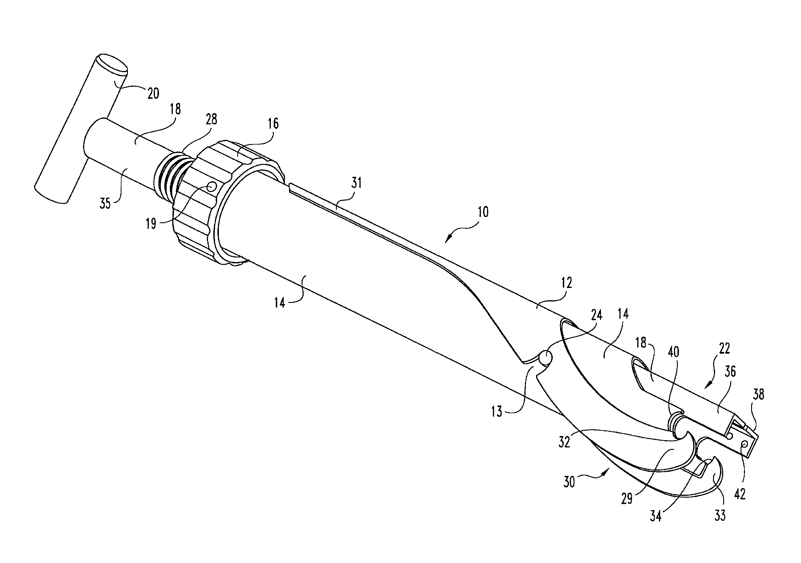
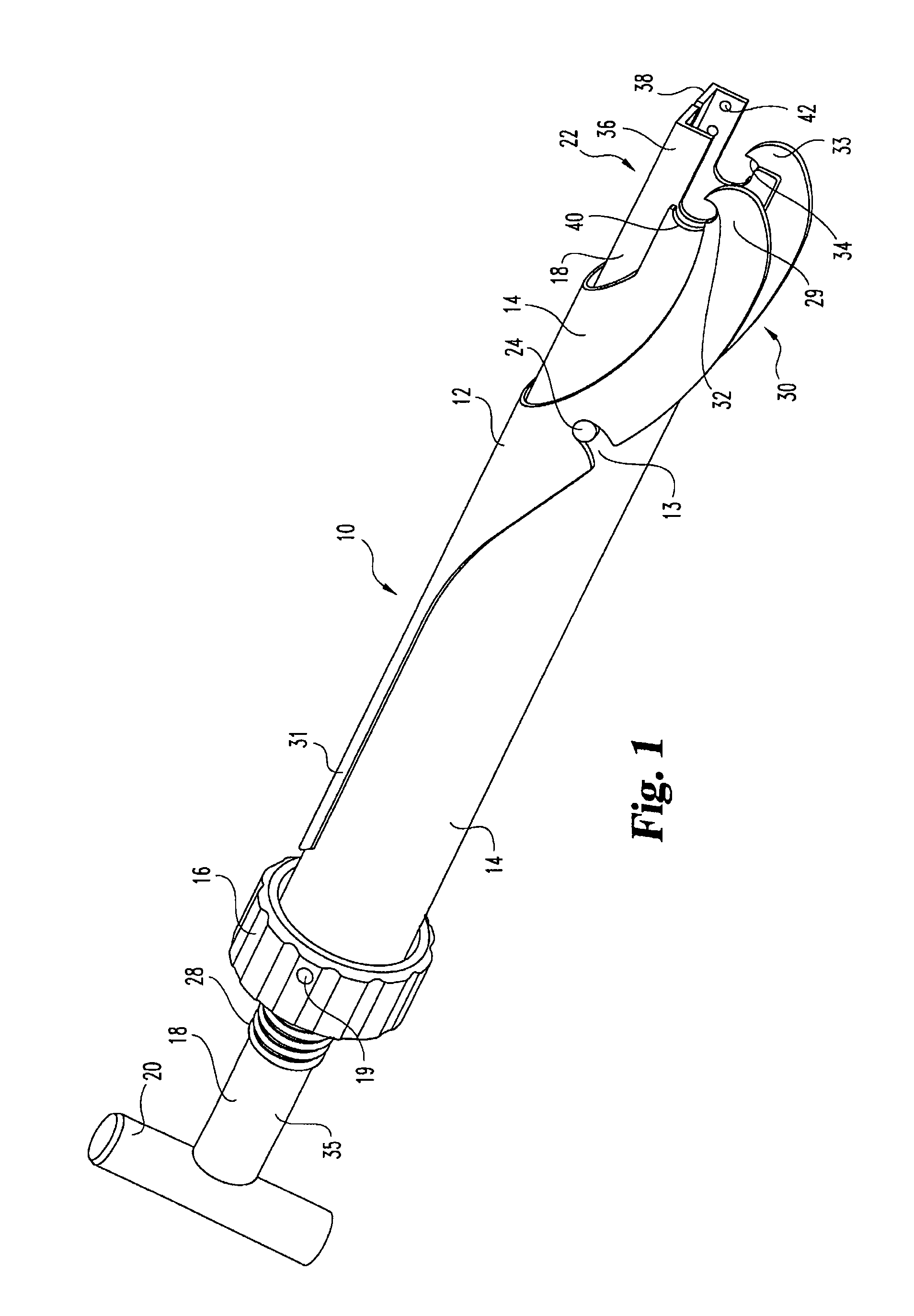
[0050]Referring now to FIG. 1, a rod introduction apparatus 10 according to the present invention includes an outer sleeve 14, a clamp shaft 18 and a lateral approximator lever 12. As will be appreciated by the detailed description that follows, the rod introduction apparatus is a multiple action device having the capability of securely holding an implant (often a hook or a screw), aligning a laterally offset l...


PUM


Abstract

An introduction apparatus for approximating a longitudinal member and an implant to permit fixation therebetween. The introduction apparatus having a gripping nose for securely engaging an implant, a lateral approximation mechanism for laterally aligning an implant and an offset longitudinal member, and a reduction mechanism for reducing the vertical distance between the implant and the longitudinal member. The introduction apparatus is provide with a gripping nose actuated by axial movement of a clamping shaft in an outer sleeve. The clamping shaft further includes an axial cannula for passage of a fastener to the implant.

Description

[0001]This application is a reissue of U.S. Pat. No. 5,910,141, issued on Jun. 8, 1999, which is hereby incorporated by reference, as if fully set forth herein. U.S. Pat. No. 5,910,141 matured from U.S. application Ser. No. 08 / 798,092, filed Feb. 12, 1997.BACKGROUND OF THE INVENTION[0002]1. Description of the Prior Art[0003]The present invention relates generally to instruments used to manipulate orthopedic implants. More particularly, the present invention relates to the manipulation of hone anchoring elements positioned in the spine and longitudinal members interconnecting those elements. While the present invention is particularly useful in spinal surgery, it may find use in other areas of medicine as well.[0004]In many applications, particularly those relating to spinal correction techniques, it is desirable to place a series of implants in a patient's spine prior to inserting a longitudinal member (a rod or a plate) along the spine to interconnect the previously placed implants...

Claims


Application Information

Patent Timeline
IPC IPC(8): A61B17/56A61B17/88
CPCA61B17/7088A61B17/7091
Inventor MORRISON, MATTHEW M.LOVELESS, ERIC A.BRUMFIELD, DAVID L.BARKER, B. THOMASCARROLL, CATALINA J.MILLER, DAVIDPETIT, DOMINIQUE
Owner WARSAW ORTHOPEDIC INC
Why Eureka
Try Eureka