
Fluid injection nozzle

A technology of liquid injection and nozzle, which is applied to the cleaning method using liquid, the device for coating liquid on the surface, and the spraying device, etc., which can solve the problems of reducing processing efficiency, substrate vibration, and liquid injection not in the predetermined direction, etc., to achieve Effect of reducing defects and preventing contact between nozzle and surface

Active Publication Date: 2007-08-29
WEIHAI DMS OPTICAL ELECTROMECHANICAL CO LTD +1
View PDF3 Cites 0 Cited by
  • Summary
  • Abstract
  • Description
  • Claims
  • Application Information

AI Technical Summary

Problems solved by technology

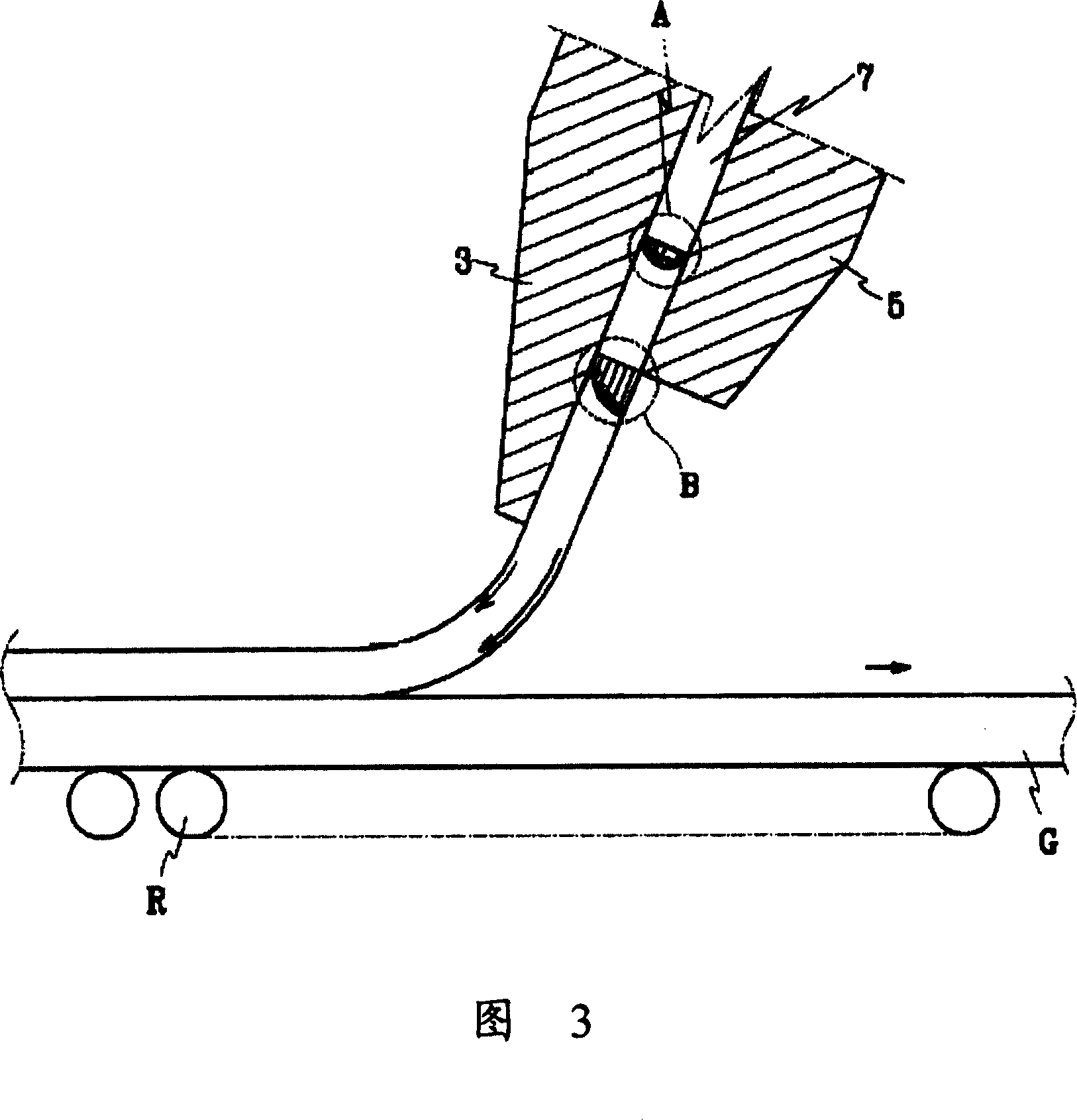
[0003] However, when the nozzle is tilted to a position such that the nozzle is positioned close to the surface, the nozzle may come into contact with the panel, which reduces processing efficiency
Also, even when the nozzle is placed at an angle, the liquid may not be injected in the intended direction
That is to say, if the injection direction of the liquid is the same as that of the plate, eddy currents and negative pressure will be generated, causing the substrate to vibrate, thereby reducing the processing efficiency

Method used


Image

  • Fluid injection nozzle
  • Fluid injection nozzle
  • Fluid injection nozzle

Examples


Embodiment Construction

[0015] In the following, preferred embodiments of the present invention illustrated in the accompanying drawings will be described in detail. Wherever possible, the same reference numbers will be used throughout the drawings to refer to the same or like parts.

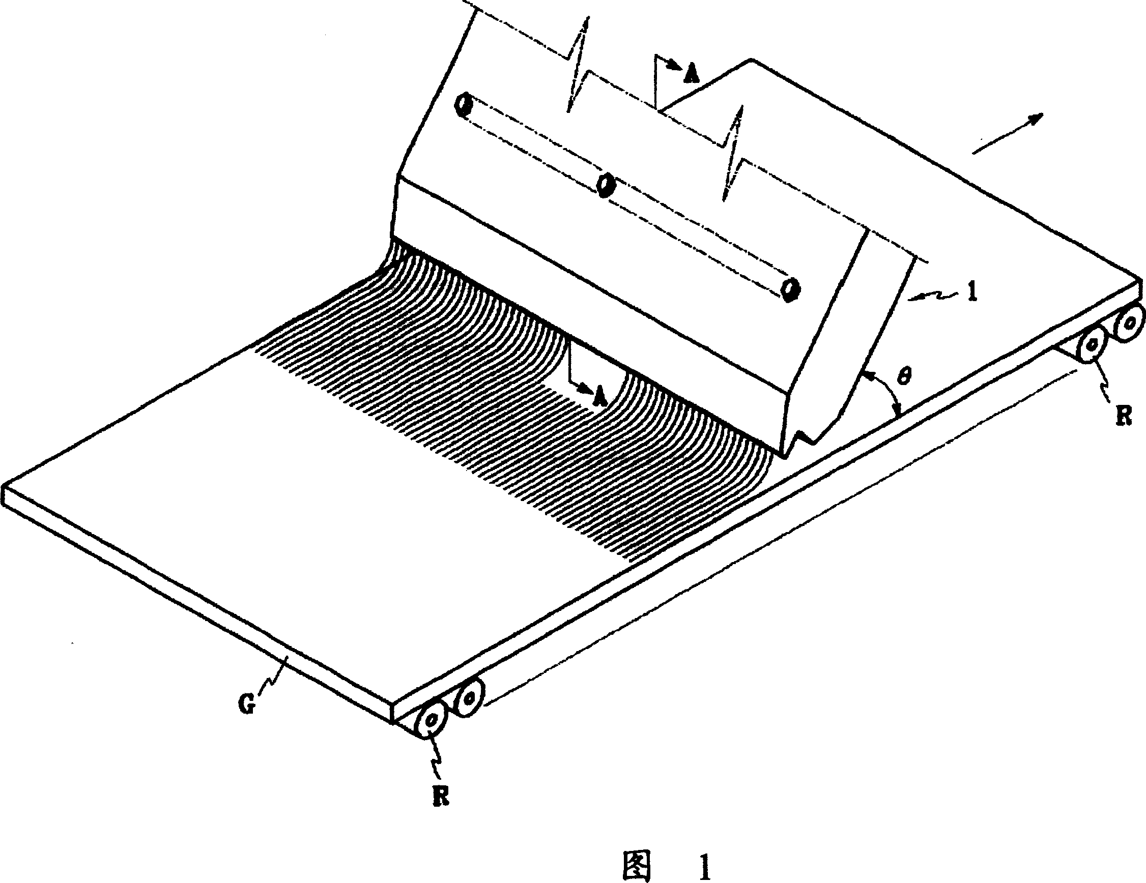
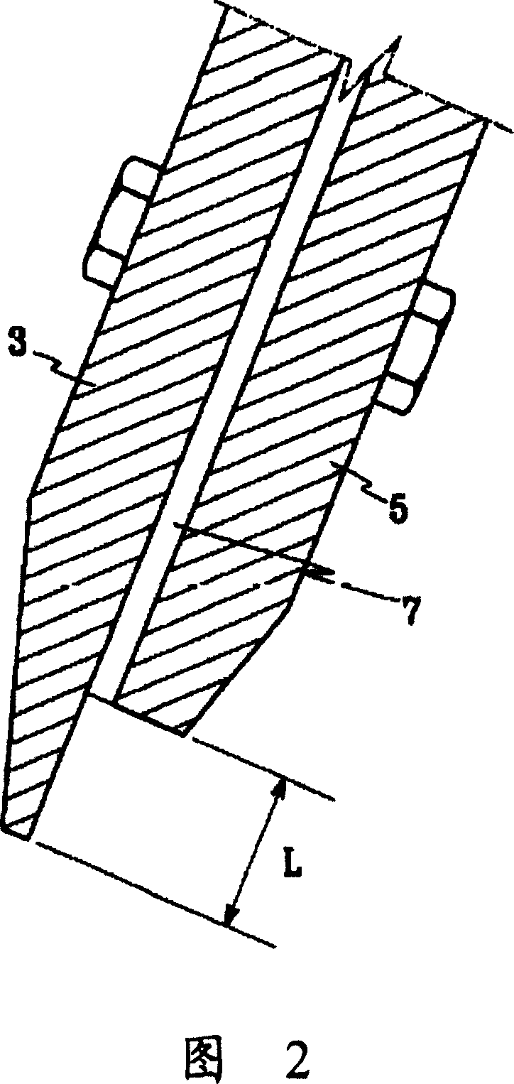
[0016] 1 and 2 show a liquid injection nozzle according to a preferred embodiment of the present invention.

[0017] The liquid injection nozzle 1 of the present invention is placed obliquely at a predetermined angle θ with respect to the surface of the substrate G. As shown in FIG.

[0018] The nozzle 1 includes a first plate 3 and a second plate 5 each having a predetermined width. The first plate 3 and the second plate 5 are connected to each other by fasteners such as screw / nut sets, between which a liquid channel 7 is defined. The length of the tip portion of the second plate 5 is shorter by L than the length of the tip portion of the first plate 3 . Furthermore, preferably, the second plate 5 is placed at the ...


PUM


Abstract

A fluid injection nozzle for treating a substrate includes a first plate having a first tip, and a second plate having a second tip, the second tip being coupled to the first plate by a fastener. The first and second plates define a fluid channel, and the first and second tips have lengths different from each other.

Description

technical field [0001] The present invention relates to a liquid injection nozzle, and more particularly to a liquid injection nozzle capable of treating the surface of a flat display panel and spraying liquid in a predetermined direction. Background technique [0002] Korean Utility Model No. 20-0305052 discloses a liquid injection nozzle for treating the surface of a flat display panel. The nozzles disclosed in this patent are designed with tips of different lengths from each other. The nozzle is placed at an inclined position relative to the surface of the flat plate to treat the surface by injecting liquid into the surface of the flat plate. By injecting liquid in a predetermined direction through inclined nozzles, the processing efficiency can be improved. [0003] However, when the nozzle is tilted to a state such that the nozzle is positioned close to the surface, the nozzle may come into contact with the panel, which reduces processing efficiency. In addition, eve...

Claims


Application Information

Patent Timeline
Patent Type & Authority Patents(China)
IPC IPC(8): B05C5/02B05B1/00B08B3/02B05B1/04B05B1/14B05B1/30B05B1/34B05C5/00F02G5/00
CPCB05C5/0254B05B1/04
Inventor 许经宪
Owner WEIHAI DMS OPTICAL ELECTROMECHANICAL CO LTD
Learn More