Supercharge Your Innovation With Domain-Expert AI Agents!

Movable microscope for detecting real-time welding of laser welding machine

A microscope and prism technology, applied in laser welding equipment, microscopes, welding equipment, etc., can solve the problems of weakening laser welding, impracticability, and inaccurate welding

Inactive Publication Date: 2007-09-05
郑 权庸
View PDF8 Cites 1 Cited by
  • Summary
  • Abstract
  • Description
  • Claims
  • Application Information

AI Technical Summary

Problems solved by technology

This has to be repeated until the entire welding operation is complete, which diminishes the advantages of laser welding for non-contact, high-speed welding
Furthermore, since it is impossible to check the welding status during the welding process, the welding is not precise enough to even achieve

Method used


Image

  • Movable microscope for detecting real-time welding of laser welding machine
  • Movable microscope for detecting real-time welding of laser welding machine

Examples


Embodiment Construction

[0022] Specific embodiments of the present invention will be described in detail below with reference to the accompanying drawings.

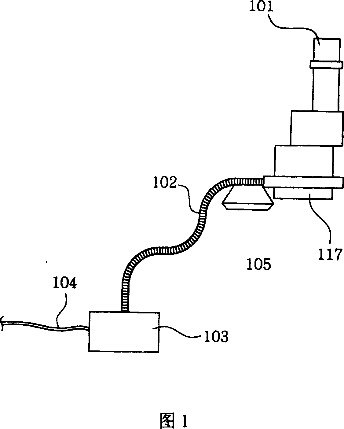
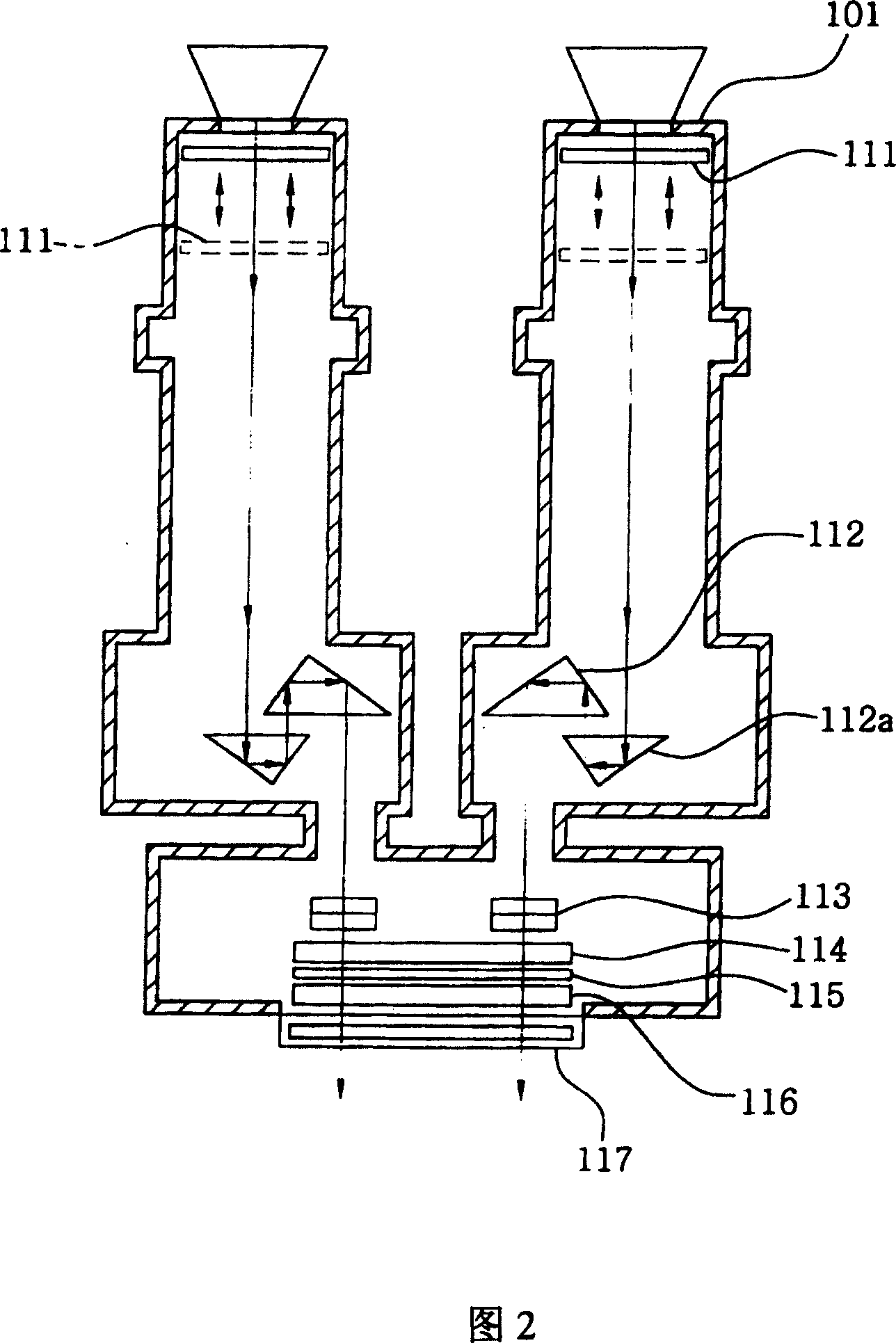
[0023] 1 is a schematic diagram illustrating the structure of a microscope connected to a flexible arm of a laser welding machine according to the present invention, and FIG. 2 is an enlarged view illustrating the structure of the microscope in FIG. 1 .

[0024] Referring to FIG. 2, the laser welding machine microscope includes a main body 101, an eyepiece 111, two pairs of prisms 112 and 112a, an objective lens 113, a liquid crystal (LC) shutter 114, a filter lens 115, a total reflection lens 116, and safety glass 117.

[0025] The main body 101 has a pair of integrally formed tubes, allowing a person to observe the welded object with both eyes simultaneously. The eyepiece 111 is movably installed in the tube of the main body 101 for adjusting the magnification of the microscope by moving up and down. Each pair of prisms 112 and 112a is instal...


PUM


Abstract

Provided is a microscope for a laser welding machine, which allows a worker to precisely inspect the weld state in an enlarged scale with the naked eye while protecting the worker's eyes from strong light such as a flash and plasma generated during a laser welding process. The microscope includes: an eyepiece movably installed in tubes of a main body, for adjusting the magnification of the microscope; a pair of prisms installed below the eyepiece, for making a welding object focused to one image; an objective lens installed below the pair of the prisms, for adjusting a focal length such that a worker sees the welding object within a worker's focal range; an LC shutter which covers and protects the objective lens when an infrared flash is generated and opens the objective lens so as to inspect the weld state in real time when the laser welding is completed; a filter lens for blocking the infrared flash generated during the laser welding; a total reflection lens installed below the filter lens, for totally reflecting a harmful wave; and a safety glass for protecting the total reflection lens from fragments generated during the laser welding. Also, the laser welding can be performed regardless of the location, size, shape, or the like of the welding object owing to the convenient mobility and easy installation and removal of the microscope.

Description

technical field [0001] The present invention relates to a microscope for inspecting real-time welding of a laser welding machine at a magnified scale, and more particularly, to a microscope for inspecting a real-time welding of a laser welding machine, which allows a worker to inspect the real-time welding of a laser welding machine at a magnified scale. It can accurately check the welding status, and at the same time protect workers' eyes from the strong light such as flash and plasma generated in the laser welding process. [0002] In addition, the present invention also relates to a microscope for accurately inspecting real-time welding of a laser welding machine, which is flexible in movement, easy to install, and easy to disassemble, regardless of the position, size or shape of the welding object. Background technique [0003] Generally, there are multiple welding methods. In recent years, among many welding methods, the laser welding method has gradually replaced the ...

Claims


Application Information

Patent Timeline
Patent Type & Authority Patents(China)
IPC IPC(8): G02B21/00B23K26/00G02B21/20
CPCG02B21/0016G02B5/281G02B21/04G02B21/20
Inventor 郑权庸
Owner 郑 权庸
Features
  • R&D
  • Intellectual Property
  • Life Sciences
  • Materials
  • Tech Scout
  • Unparalleled Data Quality
  • Higher Quality Content
  • 60% Fewer Hallucinations
Learn More