Electronic electric shock gas fly bullet

An electronic and gas technology, applied in the direction of warheads, ammunition, self-propelled bullets, etc., can solve the problems of law enforcement and security personnel being vulnerable to close-range injuries, bullets with large trauma capabilities, and high bullet ejection speeds. Improve the ability to fight crime, the effect of appropriate speed

An electronic and gas technology, applied in the direction of warheads, ammunition, self-propelled bullets, etc., can solve the problems of law enforcement and security personnel being vulnerable to close-range injuries, bullets with large trauma capabilities, and high bullet ejection speeds. Improve the ability to fight crime, the effect of appropriate speed

CN100343615CInactive Publication Date: 2007-10-17宋有洲

Image

  • Electronic electric shock gas fly bullet
  • Electronic electric shock gas fly bullet

Examples


Embodiment Construction

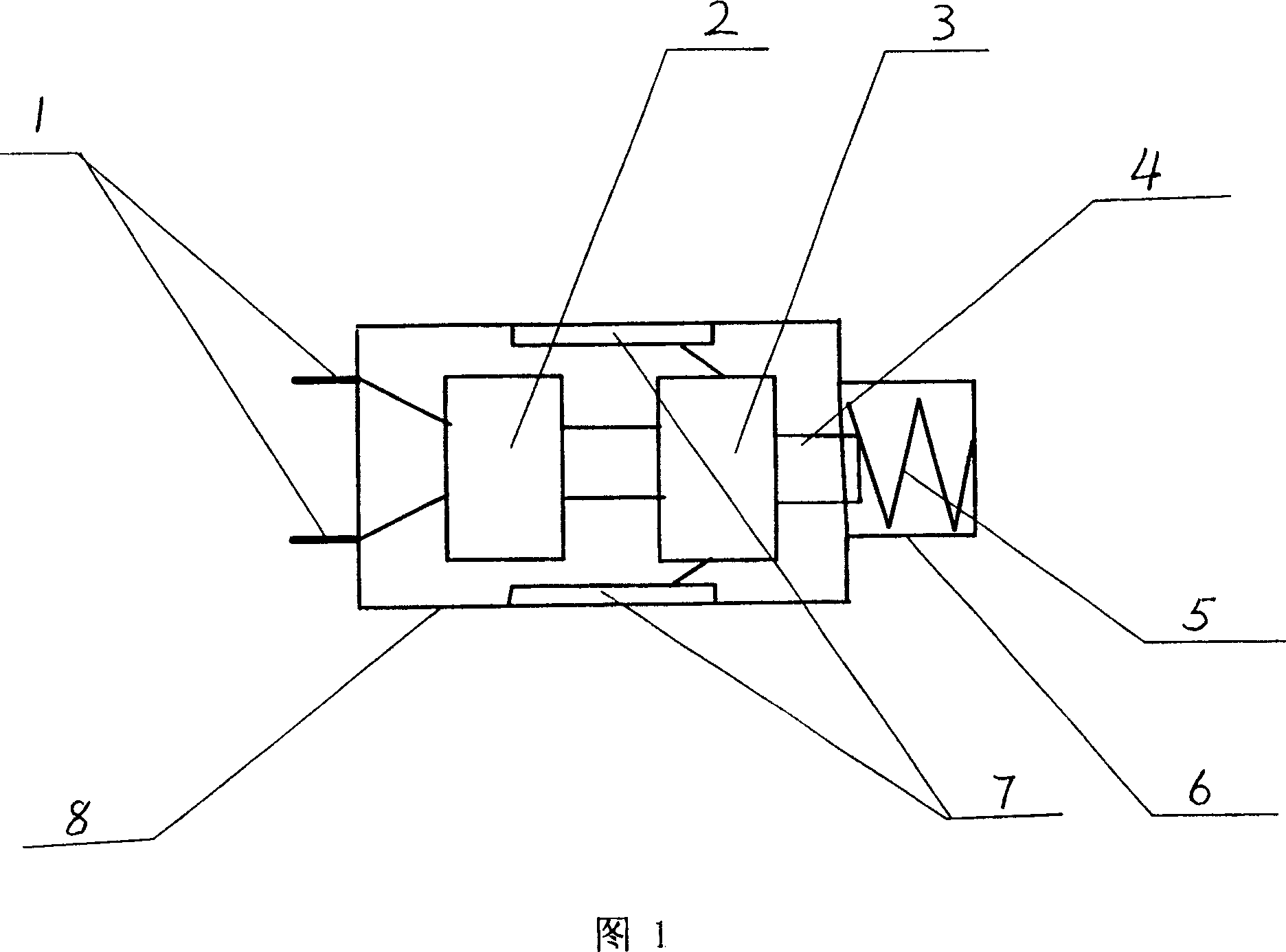
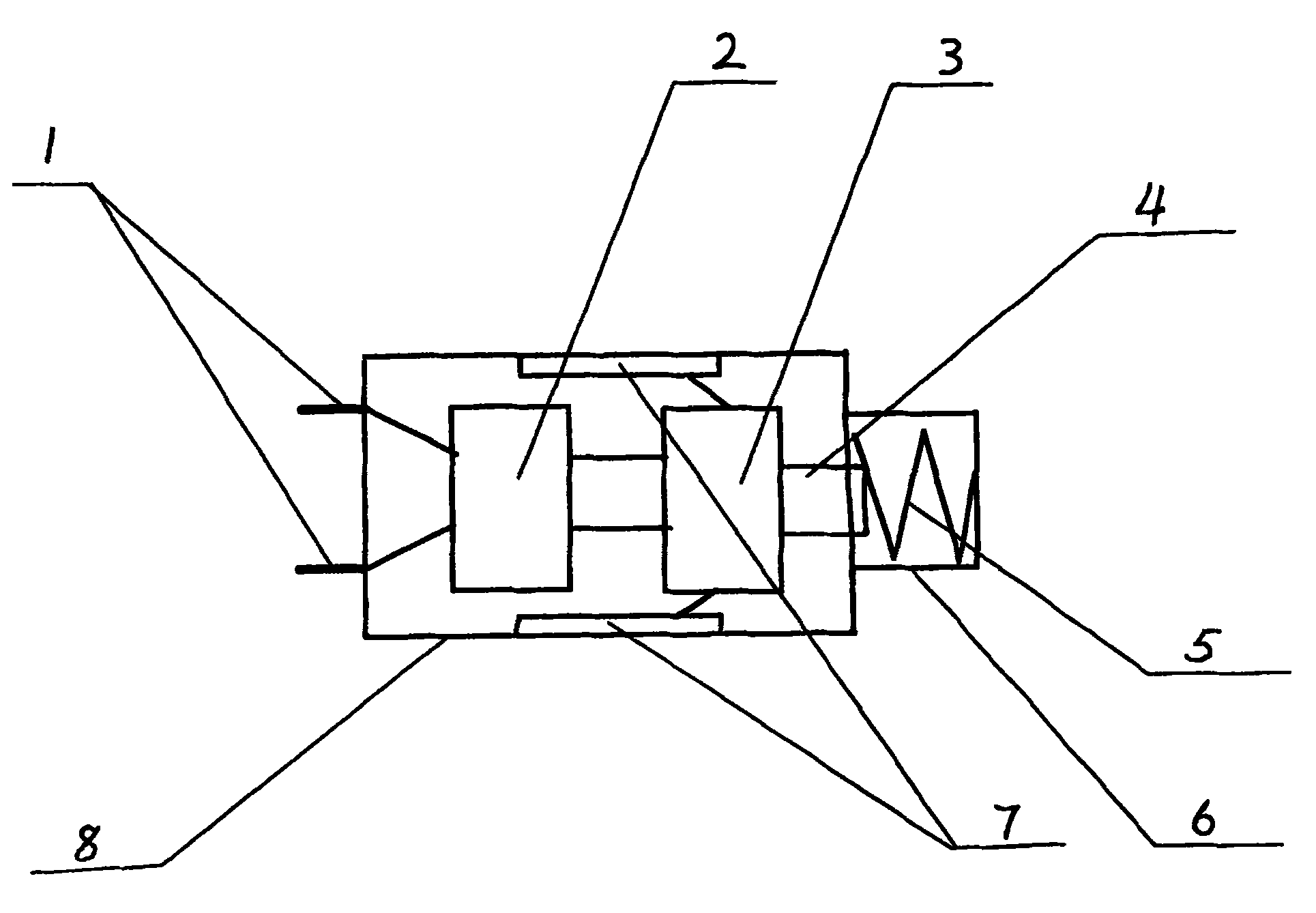
[0008] Referring to the accompanying drawings, the gas electronic electric shock missile provided by the present invention includes a casing 8 in which a rechargeable battery 3 and a high-voltage energy storage discharge circuit 2 connected to the rechargeable battery are arranged. The front end of the casing is provided with a needle-like The electrode pair 1 is provided with a flight guide 5 at the tail of the casing, the electrode pair 1 is connected to the discharge output end of the high-voltage discharge energy storage circuit 2, and the rechargeable battery 3 is provided with a charging connector for connecting to an external power supply.

[0009] The charging connectors may be two charging contacts 7 arranged on the side of the casing.

[0010] The charging connector may be a charging plug located at the rear of the casing.

[0011] A trigger switch 4 may be provided on the connection line between the rechargeable battery 3 and the high-voltage energy storage and disc...


PUM


Abstract

A pneuamtic electric-shock electronic bullet is composed of casing, rechargeable battery, high-voltage energy-accumulating and discharging circuit, front needle electrode pair, and flying tail guide. After it is shot out by its shooting device to hit the human body, high-voltage discharge takes place to electrically shock it. Its advantages are high effect and temporary damage to people.

Description

technical field [0001] The invention relates to a gas electron electric shock missile. Background technique [0002] As technology advances, illegal violence is increasingly equipped, making law enforcement and security personnel highly vulnerable to close quarters while performing their duties. Since the use of existing conventional firearms is strictly regulated, and their use among the crowd may cause serious consequences of accidental injury, people have put forward the idea of ​​developing non-harmful electric shock missiles, trying to rely on the electric shock effect of electric shock missiles on the human body to make violent activities Personnel temporarily lose their attack power, and avoid permanent damage while stopping violent activities. For example, Chinese patent application No. 89109232.3 provides an electric shock bullet and its generating device. Capacitor, the front end of the bullet is provided with a coaxial electrode connected to the capacitor, and a ...

Claims


Application Information

Patent Timeline
17 Oct 2007
Publication
CN100343615C
IPC
F42B12/36; F41B11/02; F41B11/50; F42B30/00
CPC
F41H13/0031; F42B12/36
Inventors
宋有洲