
Device for measuring the injection amount in injection systems and method for production thereof

A technology of injection system and injection quantity, applied in the direction of measurement device, fuel injection device, charging system, etc., can solve the problems of measurement results and measurement accuracy change, impossible measurement, slow decay, etc., to improve measurement accuracy and improve stability. , the effect of reducing deformation

Inactive Publication Date: 2007-11-07
ROBERT BOSCH GMBH
View PDF6 Cites 2 Cited by
  • Summary
  • Abstract
  • Description
  • Claims
  • Application Information

AI Technical Summary

Problems solved by technology

[0003] But this known injection quantity indicator has some disadvantages
Especially short and violent injection pulses will cause the piston to vibrate, but its decay is relatively slow, so it is difficult or even impossible to measure the rapid injection before and after
In addition, when the piston moves in the cylinder, friction occurs on the walls in contact with each other, so that the movement of the piston does not always reflect the actual injection volume under certain conditions
In addition, the piston and cylinder combination is also subject to wear, so the measurement results and measurement accuracy may change during the service life of the device

Method used


Image

  • Device for measuring the injection amount in injection systems and method for production thereof
  • Device for measuring the injection amount in injection systems and method for production thereof

Examples


Embodiment Construction

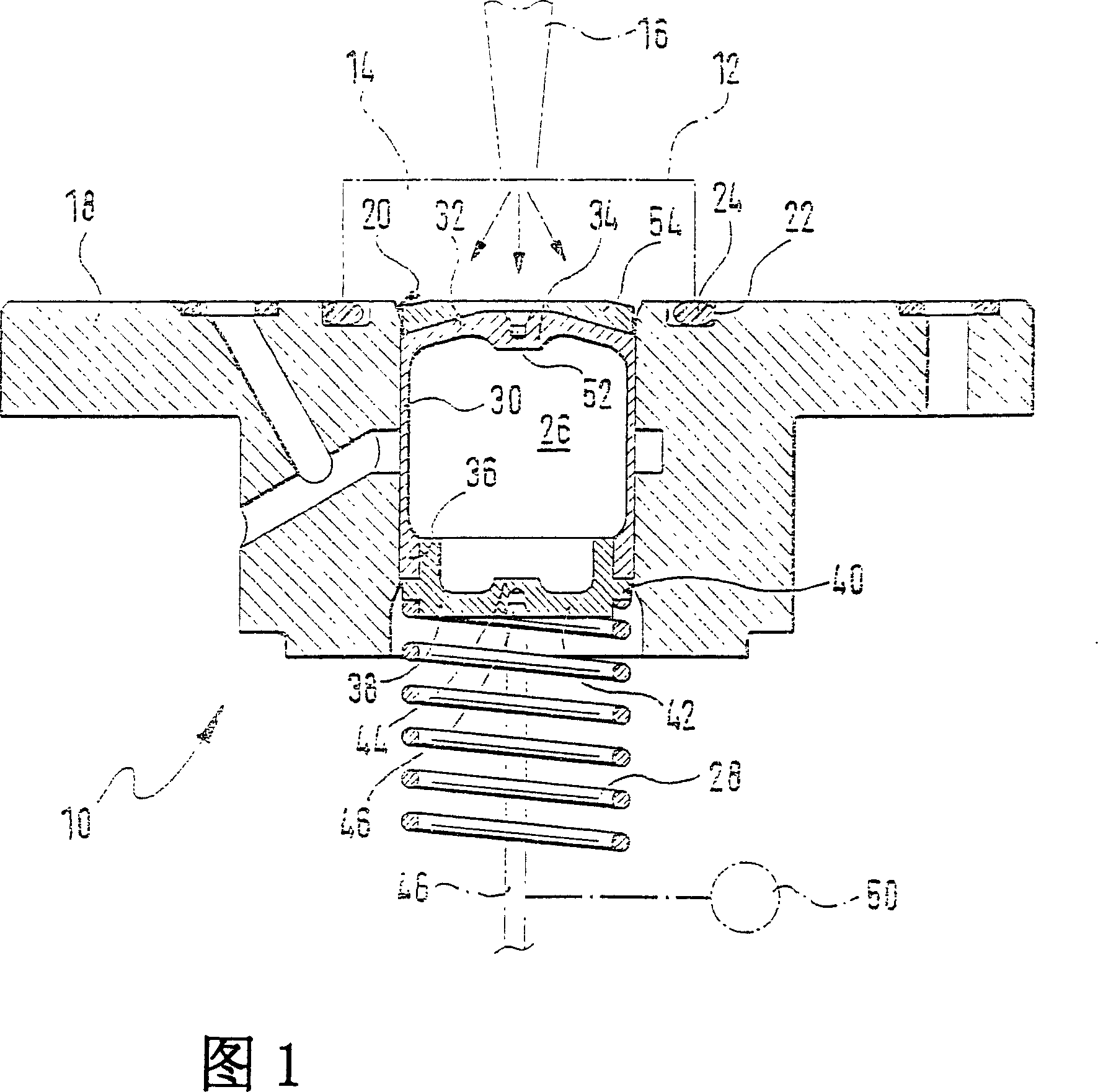
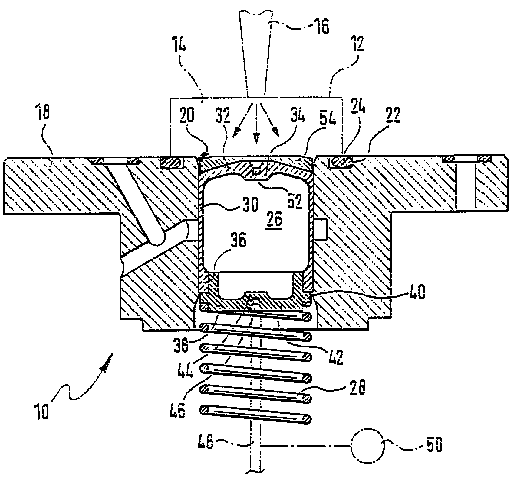
[0021] Said device is referenced 10 in FIG. 1 . It comprises a measuring chamber 14 formed in a housing 12 , to which a nozzle 16 is connected in a sealing manner. In this figure the housing 12, the measuring chamber 14, and the nozzle 16 are only schematically indicated with dotted lines.

[0022] On the lower side in FIG. 1 the measuring chamber 14 is bounded by a guide cylinder 18 , wherein in its plan view, ie viewed from the top in FIG. 1 , the cylinder is a cylindrical rotating part. Cylinder 18 has a concentric pilot bore 20 . An annular groove 22 is formed coaxially with the guide hole 20 in the upper surface of the cylinder 18, in which a sealing ring 24 is placed. Via this sealing ring 24 , the housing 12 forms an airtight connection with the cylinder 18 .

[0023] A piston 26 is movably held in the guide bore 20 of the cylinder 18 . The piston 26 is prestressed upwards, ie towards the measuring chamber 14 , by a spring 28 . Piston 26 essentially comprises a cyl...


PUM


Abstract

A device (10) serves for the measurement of the injection amount from injection systems (16), in particular for motor vehicles and in particular in the production check. The device (10) comprises a measuring chamber (14), a coupling device, by means of which at least one injection system (16) may be coupled to the measuring chamber (14) in a sealed manner. The device (10) further comprises a piston (26), retained in a displaceable manner in a guide device (18) and which partially defines the measuring chamber (14). Furthermore, another sensor (50) is provided, which, on an injection by the injection system (16), measures a displacement of the piston (26). According to the invention, the accuracy may be increased, whereby the piston (26) is at least essentially closed and of hollow interior.

Description

technical field [0001] The invention mainly relates to a device for measuring the injection quantity of an injection system, especially for motor vehicles and especially for process inspection, which device has: a measuring chamber; a connecting device, through which at least one injection system can be connected Sealed connection to the measuring chamber; a piston, which is movably held in a guide and delimits the measuring chamber in regions; and a sensor, which detects the displacement of the piston during an injection of the injection system. Background technique [0002] Such a device is known on the market and is known as an EMI (Ejection Quantity Indicator). The device includes a cylinder in which a piston is guided. The walls of the measuring chamber are formed at least in regions by pistons. The measuring chamber also has an opening to which an injection system, for example a nozzle of an injector, is mounted in a sealable manner. If a nozzle sprays fuel or a spe...

Claims


Application Information

Patent Timeline
Patent Type & Authority Patents(China)
IPC IPC(8): F02M65/00
CPCF02M65/002F02M65/001
Inventor 约阿希姆·翁格尔拉尔夫·宾德尔拉尔夫·哈斯迪尔克·沃尔夫
Owner ROBERT BOSCH GMBH
Learn More