
Radio communication system time slot allocation method

A technology of time slot allocation and time slot number, which is applied in wireless communication, radio/induction link selection and arrangement, electrical components, etc.

Inactive Publication Date: 2007-11-21
MITSUBISHI ELECTRIC CORP
View PDF7 Cites 0 Cited by
  • Summary
  • Abstract
  • Description
  • Claims
  • Application Information

AI Technical Summary

Problems solved by technology

[0005] Since the conventional time slot allocation method is configured as described above, there is a problem that the user station cannot request an arbitrary number of time slots.
Also, even if an arbitrary number of time slots can be requested, in the case where some subscriber stations require a large number of time slots, depending on the time slot allocation method, there are times when the communication time slots on the wireless line are occupied by some user stations, and TDMA wireless communication The problem of time slot allocation deviation such that the communication of other user stations in the system is rejected or interrupted

Method used


Image

  • Radio communication system time slot allocation method
  • Radio communication system time slot allocation method
  • Radio communication system time slot allocation method

Examples


Embodiment Construction

[0026] Hereinafter, the present invention will be described in more detail, and the best mode for carrying out the present invention will be described with reference to the drawings.

[0027] Embodiment 1

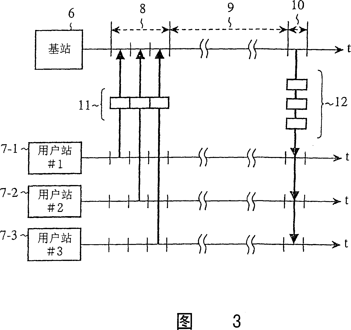
[0028] Fig. 11 is a block diagram showing a radio communication system according to Embodiment 1 of the present invention. FIG. 11 shows a case where three subscriber stations exist within the communication range of the base station. Among Fig. 11, 6 is a base station, and 7 is 3 user stations that send and receive data with the base station 6 through wireless lines, and 19-1, 19-2, and 19-3 are temporarily stored respectively from the network connected to the base station 6 (not shown). ) a downlink transmission buffer for downlink transmission data to each terminal device (not shown) connected to each user station. 50-1, 50-2, and 50-3 are uplink transmission buffers for temporarily storing uplink data from each terminal device to the network, and 51 is a base station i...


PUM


Abstract

When the total number of transmission request time slots for a base station and a subscriber station exceeds the number of communication time slots on the radio line, the ratio of number of communication time slots against the total number of transmission request times slots from the base station and the subscriber station is calculated and the number of time slots allocated for each subscriber station is determined by a product of a total number and ratio of the transmission request time slots from the subscriber station.

Description

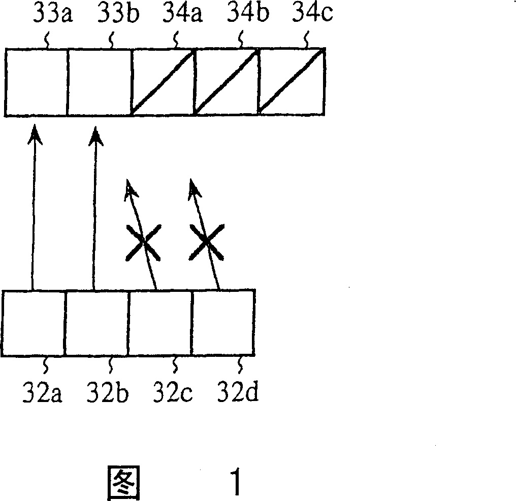
field of invention [0001] The present invention relates to a method for allocating time slots in a radio communication system using radio lines in a TDMA system composed of a base station and a plurality of subscriber stations. Background technique [0002] Fig. 1 shows the time slot allocation method figure of existing wireless communication system, among the figure, 32a, 32b, 32c, 32d are the transmission request that 4 user stations send, 33a, 33b are the vacant time slots of communication of base station, 34a, 34b, 34c are time slots where the base station is communicating. [0003] The operation will be described below. [0004] In the existing time slot allocation method, when the number of vacant time slots for base station communication is more than the number of subscriber stations with new transmission requirements, the time slots for communication from the base station to the subscriber stations and the time for communication from the subscriber station to the ba...

Claims


Application Information

Patent Timeline
Patent Type & Authority Patents(China)
IPC IPC(8): H04Q7/36H04W72/04H04W72/12H04W74/04
CPCH04W72/0446
Inventor 村本英司佐藤刚毅川端孝史丰田教彦
Owner MITSUBISHI ELECTRIC CORP
Learn More