Apparatus and method for radial and angular or rotational analysis or images for shape content and matching

A shape-content, radial-like technique for use in spatial light modulators

Inactive Publication Date: 2007-12-12
OCULAR DYNAMICS
View PDF7 Cites 0 Cited by
  • Summary
  • Abstract
  • Description
  • Claims
  • Application Information

AI Technical Summary

Problems solved by technology

However, it still has some disadvantages
For example, the spatial frequency resolution of the image in each angular direction of the rotating slit is not as good as may be required in some applications or uses of this system
Also, a rotating mask or wheel map with associated drives such as all mechanical equipment has stability and long-term reliability challenges, not to mention size and weight requirements

Method used


Image

  • Apparatus and method for radial and angular or rotational analysis or images for shape content and matching
  • Apparatus and method for radial and angular or rotational analysis or images for shape content and matching
  • Apparatus and method for radial and angular or rotational analysis or images for shape content and matching

Examples


Embodiment Construction

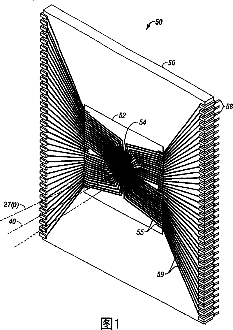
[0030] A kind of segmented radial spatial light modulator (SLM) device 50 according to the present invention is schematically shown in FIG. Optical zone 54. As shown schematically in FIG. 1 , the segmented radial SLM device 50 is preferably, but not necessarily, constructed as an integrated circuit 52 mounted on a chip 56 equipped with components for insertion into a printed circuit board (not shown). A plurality of electrical pins 58 in correspondingly disposed jacks (not shown). In this preferred embodiment, the pins 58 are electrically connected by a plurality of wires 59 soldered to contact pads 55 of the integrated circuit 52 so that the optical components in the active optical region 54 can be addressed and operated, as will be described below. Detailed in the text.

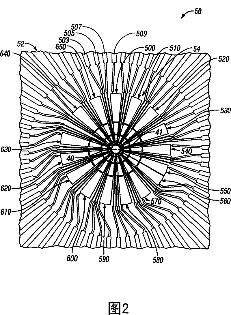
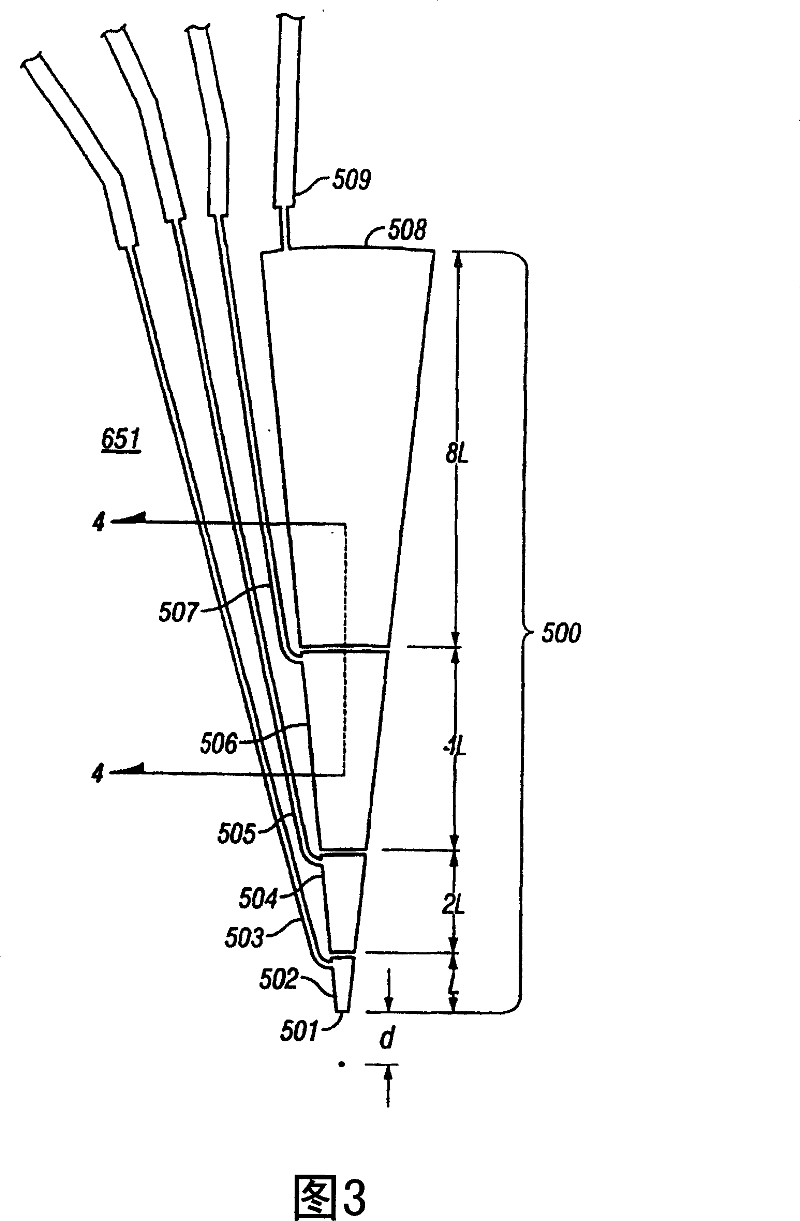
[0031]An enlarged front view of the active optical region 54 of the integrated circuit 52 is shown in FIG. 2, and a modulator sector 500 of the active optical region 54 is shown in FIG. An even more enla...


PUM


Abstract

A segmented radial spatial light modulator has an active optic area comprising a plurality of radially extending active optic modulators disposed at various angular orientations with respect to a central axis. The segmented radial spatial light modulator is used in separating and isolating portions of Fourier transform optic patterns from images for characterization of images by shape for recording, storing, retrieving, searching, and comparison to other images for matches and near matches. The images can be ghosted to increase optical power in the Fourier transform optic pattern without adding new shape content and for grading comparisons to other image shape characteristics for identifying near matches in addition to matches.

Description

[0001] Related Patent Applications [0002] This patent application is a continuation-in-part of U.S. Patent Application Serial No. 09 / 536,426, filed March 27, 2000, in the United States Patent and Trademark Office, which is U.S. Patent Application Serial No. 09, filed June 4, 1999 Continuation of / 326,362. technical field [0003] This application relates generally to spatial light modulators, and in particular to active light modulation sectors with radiation directions for radial and angular analysis of beams, including Fourier transform optical patterns, for applications such as characterization, searching, matching Or recognize the shape content of an image. Background technique [0004] There are cases where useful information can be derived from spatially dispersed beam parts. In particular, when an image is carried or propagated by a beam of light, it may be useful to collect and use or analyze information on specific portions of the image, such as specific portion...

Claims


Application Information

Patent Timeline
Patent Type & Authority Patents(China)
IPC IPC(8): G06K9/58G06F17/30G06T7/00G06V10/88H04N5/76H04N5/92
CPCG02F2203/50G06K9/522G06F17/30247G06K9/74G02F1/133362G02B27/46G06T7/00G06K9/58G02F1/134309G06K9/748G02F1/13306G02F2203/12G06F16/583G06V10/431G06V10/88G06V10/92
Inventor 里克·克里勒
Owner OCULAR DYNAMICS
Why Eureka
Try Eureka