Vehicle heating device and method for assembling a vehicle heating device
A technology for heating devices and vehicles, which is applied in combustion methods, electromechanical devices, vehicle components, etc., to achieve the effect of reasonable cost and easy installation
- Summary
- Abstract
- Description
- Claims
- Application Information
AI Technical Summary
Problems solved by technology
Method used
Image

Examples
Embodiment Construction
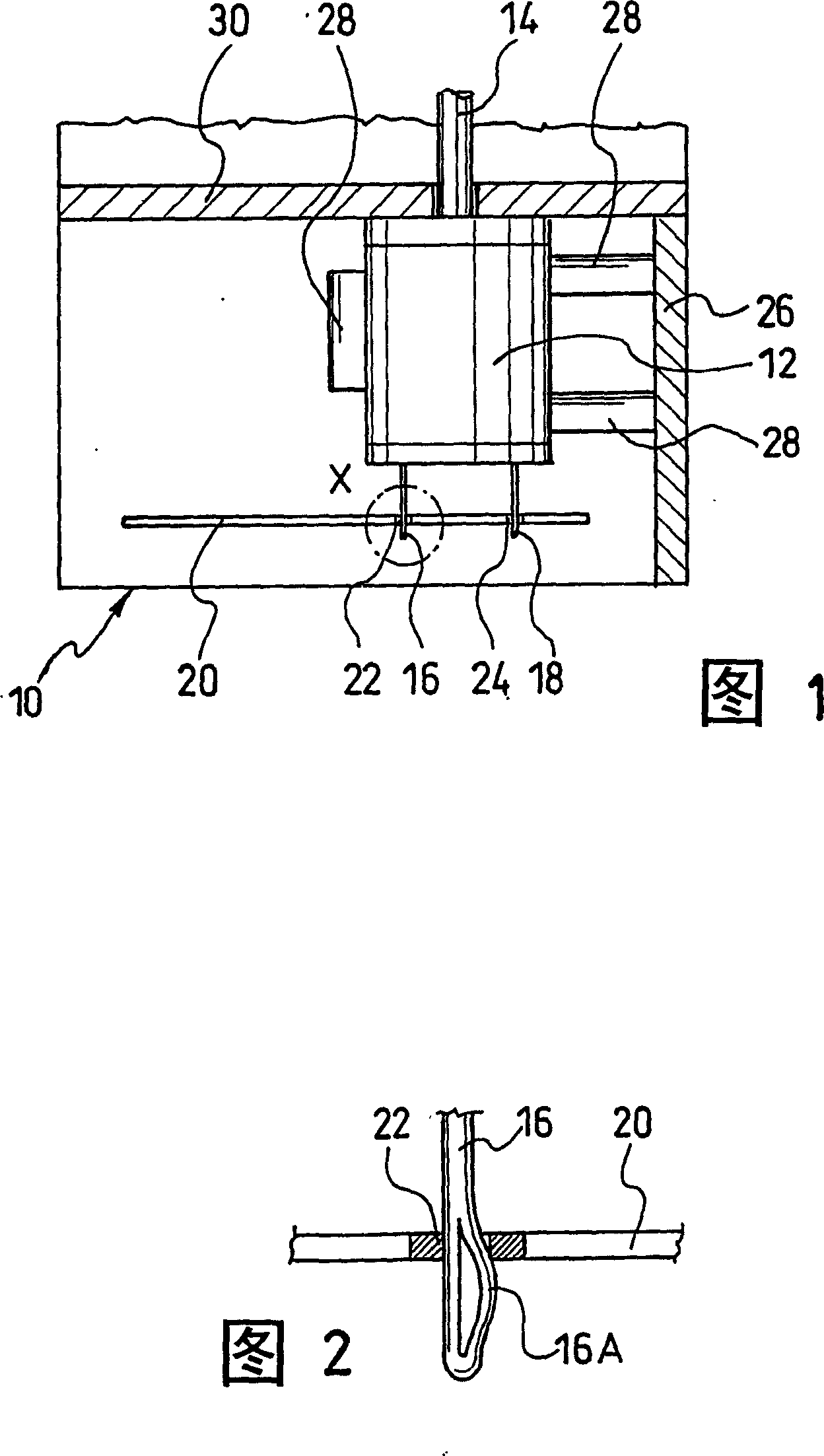
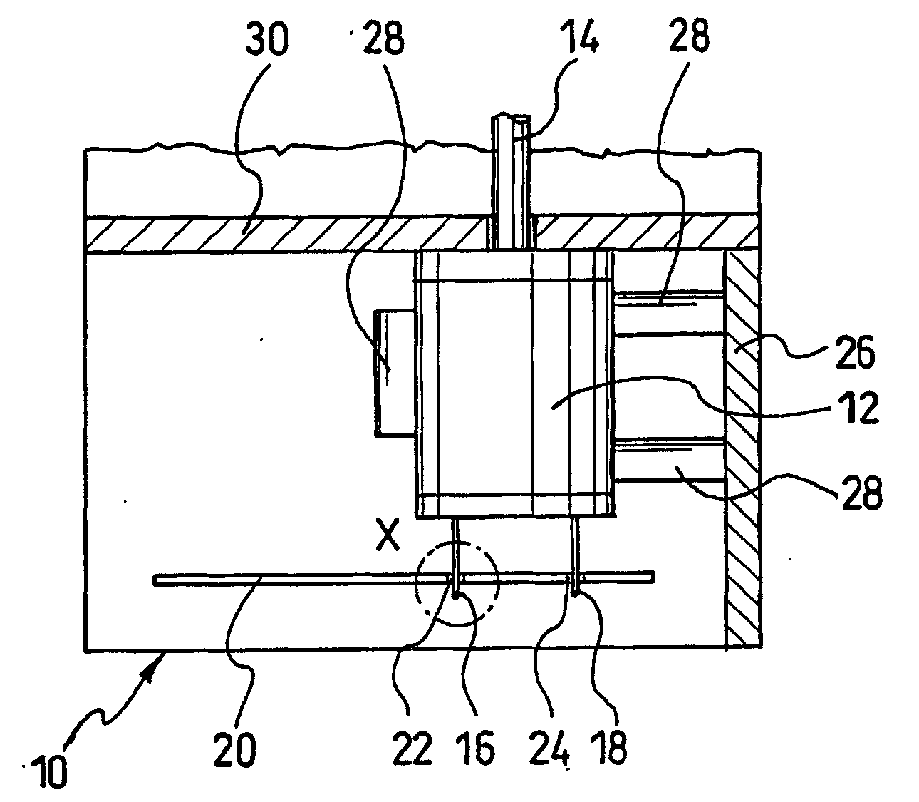
[0022] FIG. 1 shows a schematic view of a portion of a combustion air blower housing 10 . A combustion air blower motor 12 is accommodated in the combustion air blower housing 10 , which drives a shaft 14 . The combustion air blower motor 12 is directly connected via two outwardly extending contacts 16 , 18 to corresponding contacts 22 , 24 on the base plate 20 of the controller. This connection can be achieved by guiding the spring-loaded contacts 16 , 18 into corresponding holes in the corresponding conductor track forming the corresponding contacts 22 , 24 . This elastic preloading can be achieved by forming a corresponding spring leaf 16A on the contact 16 itself (see FIG. 2, corresponding to the part X in FIG. 1) or by making the distance of the contacts 16, 18 relative to the corresponding contact 22, 24 in slight deficiency or excess to achieve. If necessary, the combustion air blower motor 12 is additionally connected mechanically to at least one wall of the combusti...
PUM
 Abstract
Description
Claims
Application Information
 - Generate Ideas
- Intellectual Property
- Life Sciences
- Materials
- Tech Scout
- Unparalleled Data Quality
- Higher Quality Content
- 60% Fewer Hallucinations
Browse by: Latest US Patents, China's latest patents, Technical Efficacy Thesaurus, Application Domain, Technology Topic, Popular Technical Reports.
© 2025 PatSnap. All rights reserved.Legal|Privacy policy|Modern Slavery Act Transparency Statement|Sitemap|About US| Contact US: help@patsnap.com