Eureka AIR delivers breakthrough ideas for toughest innovation challenges, trusted by R&D personnel around the world.

Panel module of optical disk drive

A technology for panel modules and optical disc drives, applied to instruments, record carrier structural parts, data recording, etc., can solve the problems of increasing material costs, inability to properly fit the casing 11, and reducing economic benefits

Inactive Publication Date: 2008-02-06
QUANTA STORAGE INC
View PDF2 Cites 0 Cited by
  • Summary
  • Abstract
  • Description
  • Claims
  • Application Information

AI Technical Summary

Problems solved by technology

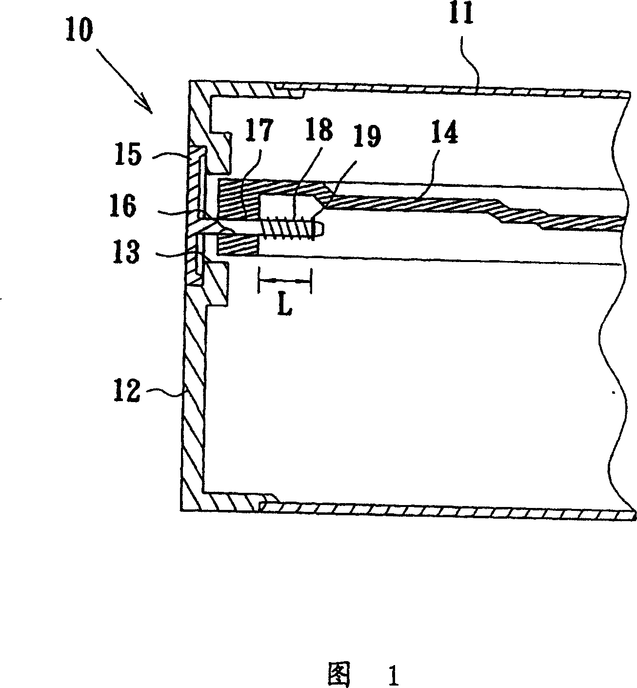
[0005] However, due to the structural characteristics of the coil spring 18, when the coil spring 18 is fully compressed, there is still the stacked length of the coil spring 18 itself, so that the panel 15 can extend the telescopic stroke L, and it is still necessary to deduct the coil spring 18. Therefore, the effective telescopic stroke of the panel 15 will be reduced, resulting in a reduction in the types of applicable casings, which not only reduces the economic benefits of mass production, but also requires a different panel to be used for a large gap in the telescopic stroke.
In addition, for the same telescopic stroke, the sliding rod 16 also needs to add the stacked length of the coil spring 18 itself, which requires a large structural space, which hinders the development trend of miniaturization of optical disc drives.
Furthermore, the too long guide hole 17 guides the sliding rod 16 to move in a fixed direction, and also restricts the angle adjustment of the panel 15, which cannot properly fit the front side 12 of the casing 11, and cannot prevent dust pollution and vibration noise.
At the same time, the nut 19 is used to lock and fix the panel 15, which not only takes time to assemble but also increases the cost of materials

Method used


Image

  • Panel module of optical disk drive
  • Panel module of optical disk drive
  • Panel module of optical disk drive

Examples


Embodiment Construction

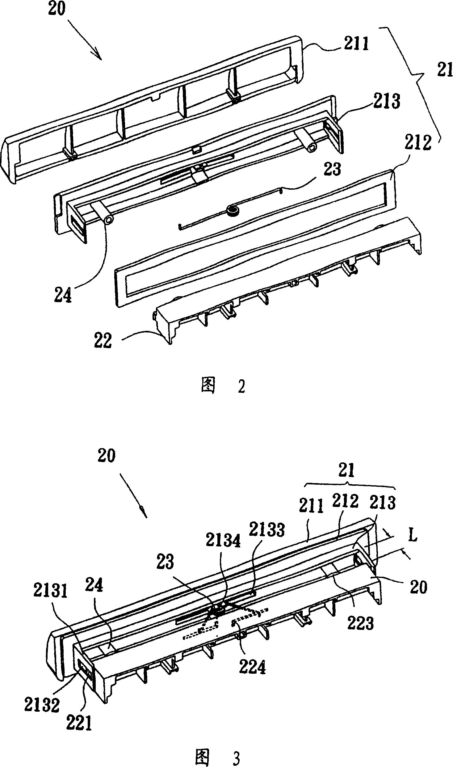
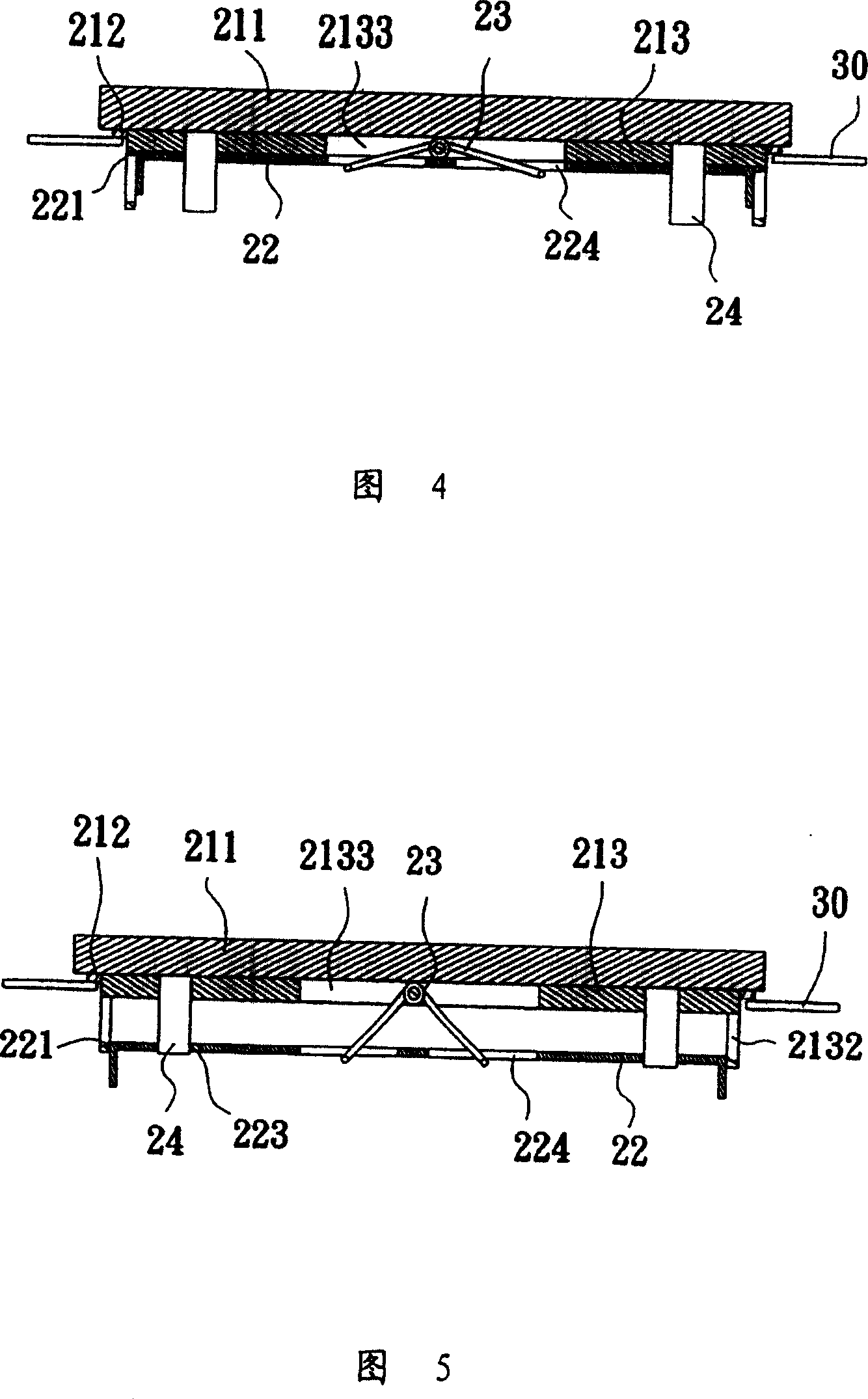
[0015] In order to achieve the above object, the present invention adopts technical means and other effects, which is a preferred embodiment, and will be described as follows in conjunction with the drawings. Please refer to FIG. 2 , the optical disc drive panel module 20 of the present invention mainly includes a panel 21 , a base 22 , a torsion spring 23 and a plurality of sliding bars 24 . The torsion spring 23 is fixed on the back of the panel 21 , and both ends are slidably connected to the base 22 , so that the base 22 moves back and forth along the slide bar 24 under the elastic force of the torsion spring 23 .

[0016] Wherein, the front panel 21 of the optical disc player panel module 20 is a decorative plate 211, the shape and style of the decorative plate 211 can be designed to meet the needs of various models of optical disc drives, and an elastic pad 212 is glued on the back of the decorative plate 211, elastic The pad 212 can be sponge, rubber or the like. A II-...


PUM


Abstract

The invention relates to a disc plane module which comprises a plane whose front has an inscribed board, wherein the back of the inscribed board attaches an elastic pad; it extents a plurality of slide rods from the plane back; a guiding seat with the groove hole is fixed on the plane back; a torsion spring is fixed in the groove hole; a base arranges a plurality of slide holes; at least one line groove is positioned on the base; the edge of the torsion spring can inset into the line groove to add the flexible traveling of the disc plane module.

Description

technical field [0001] The invention relates to a panel of an optical disc drive, in particular to a panel module in the optical disc drive with a relatively long stretching stroke. Background technique [0002] Since the optical disc drive uses a high-speed and high-density storage disk to quickly search and read or record data with a precision laser head, it is necessary to prevent dust pollution and vibration and noise caused by rapid movement to maintain The accuracy of the optical disc drive, and the close-fitting structure of the panel of the optical disc drive directly affects the prevention of dust, vibration and noise of the optical disc drive. [0003] As shown in FIG. 1 , the existing optical disc drive 10 is provided with an access hole 13 on the front side 12 of the casing 11, allowing the tray 14 carrying the disk to freely extend out of the casing 11 to exchange disks, or to store it in the casing 11. to play within. Wherein the front end of the tray 14 is c...

Claims


Application Information

Patent Timeline
Patent Type & Authority Patents(China)
IPC IPC(8): G11B33/00G12B9/10
Inventor 陈炫坤
Owner QUANTA STORAGE INC
Why Eureka
Eureka Blog
Learn More