
Rotating mechanism of video disk machine with liquid crystal display screen

A technology of liquid crystal display screen and rotating mechanism, which is applied to record carrier structural parts, the layout of structural parts in carrier equipment, instruments, etc., can solve problems such as large area and viewing effect interference.

Inactive Publication Date: 2008-02-13
江苏常州武新产业投资有限公司
View PDF3 Cites 0 Cited by
  • Summary
  • Abstract
  • Description
  • Claims
  • Application Information

AI Technical Summary

Problems solved by technology

However, the portable machine of this structure occupies a large area when it is opened and used, because the display auxiliary machine can only rotate relative to the main machine along the opening and closing direction to adjust the playback angle. The playback direction of the display sub-machine can only be changed by changing the direction of the portable machine including the main unit; and when playing, the main unit of the portable machine is located in front of the display sub-machine, which will interfere with the viewing effect to a certain extent

Method used


Image

  • Rotating mechanism of video disk machine with liquid crystal display screen
  • Rotating mechanism of video disk machine with liquid crystal display screen
  • Rotating mechanism of video disk machine with liquid crystal display screen

Examples


Embodiment 1

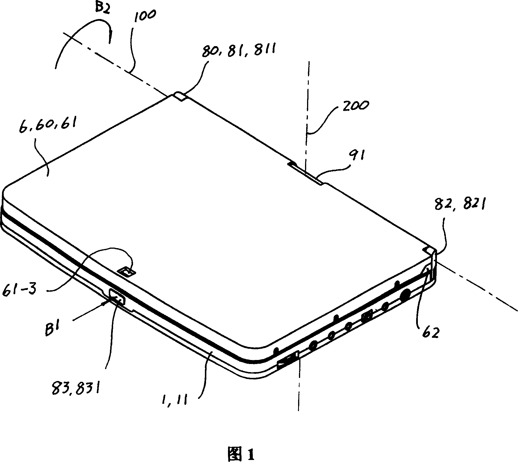
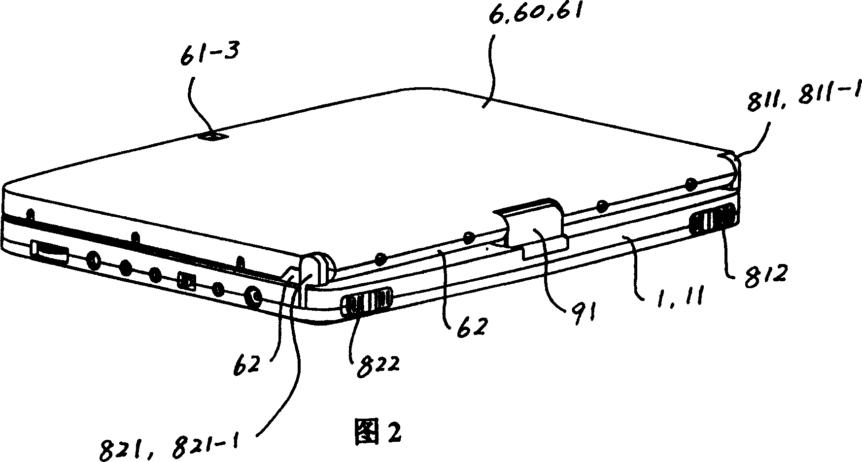
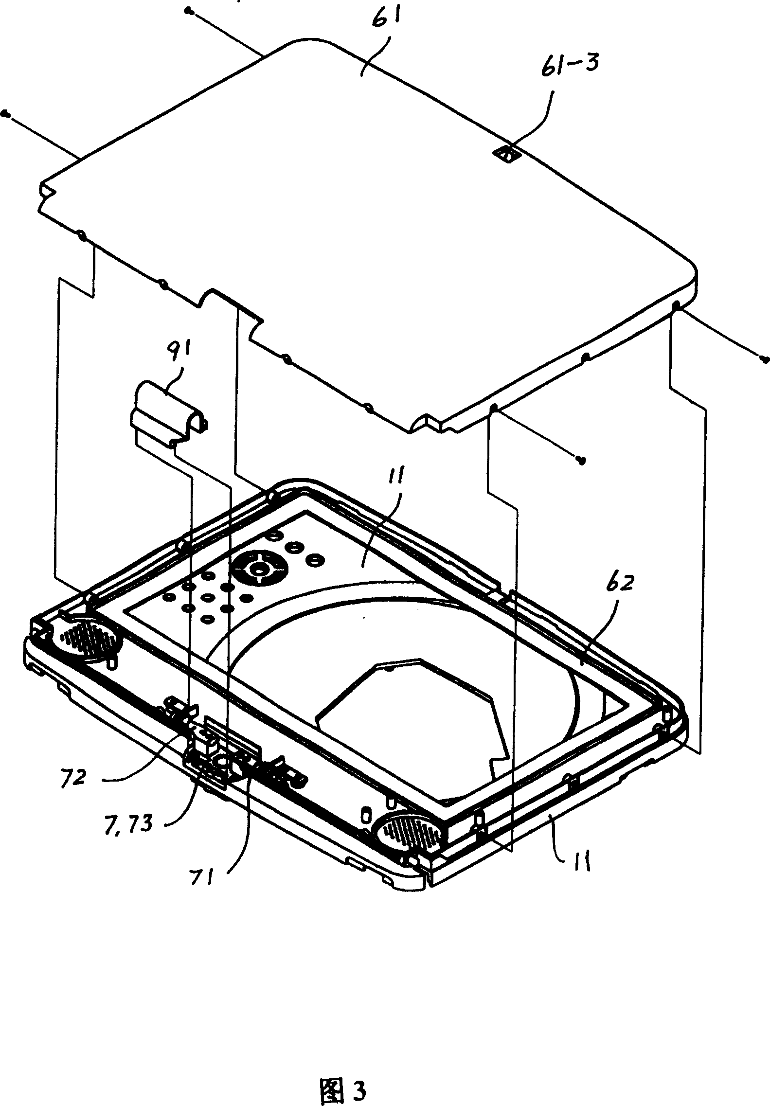
[0068] Referring to FIG. 1 to FIG. 4 , the dual-axis rotating mechanism of this embodiment has an upper seat 11 of the main machine casing, an auxiliary machine casing 60 , a rotating part 7 and a decorative cover 91 . The auxiliary machine casing 60 has a surface cover 61 and a screen cover 62 , and the surface cover 61 is fixed on the screen cover 62 to form the auxiliary machine casing 60 . The rotating part 7 is a two-axis rotating part with resistance, and the auxiliary machine casing 60 is connected with the upper seat 11 of the main casing through the rotating part 7 in a two-way direction with resistance. The decorative cover 91 is fixed with the rotating part 7 . The upper seat 11 of the main machine casing, the screen cover 62 and the decorative cover 91 of the auxiliary machine casing 60 are all plastic integral parts, the face cover 61 of the auxiliary machine casing 60 is an aluminum plate punching part, and each part in the rotating part 7 is steel parts.

[00...

Embodiment 2

[0100] See Figures 47 to 50 and Figures 1 to 4, the rotating mechanism of this embodiment is still a two-axis rotating mechanism, and the rest of the rotating mechanism is the same as that of Embodiment 1, except that the rotating parts of this embodiment 7 is structurally different from the rotating part 7 in Embodiment 1. 51 to 54, the first moving shaft rotating assembly 71 of the rotating part 7 in this embodiment has a first connecting arm 711, a first inner friction washer 712, a first rotating foot 713, a first outer friction washer 714, a first Elastic washer 715 , first outer stop washer 716 and first lock nut 717 . The second moving shaft rotating assembly 72 of the rotating part 7 in this embodiment has a second connecting arm 721, a second inner friction washer 722, a second rotating foot 723, a second outer friction washer 724, a second elastic washer 725, a second outer Stop washer 726 and second lock nut 727.

[0101] Still referring to FIG. 51 to FIG. 54 , th...


PUM


Abstract

The present invention belongs to an optic disk player mechanism with a liquid crystal display screen. In said mechanism, a center seat is set at the top table of the host body case; a turning foot stool is set at the sub machine body case; the rotating part is of double-axes, the connecting arm at the motorized axle rotating part is connected with the rotating feet in an anti-rotating mode, the common axis of the connecting arm and the rotating feet is a horizontal rotating axes; a fixed block of the fixed-axis rotation component of the double-axes rotating part is connected to a rotating block in an anti-rotating manner, and the common axis of the position block and the rotating block is a perpendicular fixed axes; the fixed block of fixed-axis rotation component is fixed at the center seat of the top table, and the perpendicular fixed axes thereon and the central line of the center seat is the same beeline; the connecting arm of the motorized axle rotating component is in permanent connection the rotating block of the fixed-axis rotation component, the rotating feet of the motorized axle rotating component are fixed at the turning foot stool of the sub machine body case. The displaying sub machine of the optic disk player adopting the present invention is capable of rotating at two directions relative to the host and at the same time, then the playing direction of the displaying sub machine can be regulated expediently.

Description

technical field [0001] The invention relates to a mechanism of a video disk player with a liquid crystal display. Background technique [0002] Existing video disc players with liquid crystal displays are portable video disc players (hereinafter referred to as portable machines). The portable machine has a main machine and a display auxiliary machine, and the display auxiliary machine is connected with the main machine through a damped rotating assembly with a horizontal fixed axis; The portable is closed. When the display auxiliary machine is disengaged from the buckle of the main machine, the display auxiliary machine can be rotated within the range of 0 degrees to 150 degrees relative to the main machine (there are also a small number of portable machines that can rotate within the range of 0 degrees to 180 degrees) . When the portable machine is in use, the main machine can be positioned on a horizontal plane such as a desktop, and the display auxiliary machine can be...

Claims


Application Information

Patent Timeline
Patent Type & Authority Patents(China)
IPC IPC(8): G11B33/00G11B33/12
Inventor 秦志尚虞立新
Owner 江苏常州武新产业投资有限公司
Learn More