Elevator equipment

A technology of elevators and driving devices, which is applied in hoisting devices, transportation and packaging, elevators, etc., and can solve the problems that the car cannot stop smoothly and the traction force is small

Inactive Publication Date: 2008-03-05
MITSUBISHI ELECTRIC CORP
View PDF6 Cites 0 Cited by
  • Summary
  • Abstract
  • Description
  • Claims
  • Application Information

AI Technical Summary

Problems solved by technology

However, it is considered that in such an elevator device with high traction capacity, even if the counterweight collides with the buffer and stops, the reduction in traction force is small and the car cannot stop smoothly.

Method used


Image

  • Elevator equipment
  • Elevator equipment
  • Elevator equipment

Examples


Embodiment Construction

[0014] Hereinafter, preferred embodiments of the present invention will be described with reference to the drawings.

[0015] [Embodiment 1]

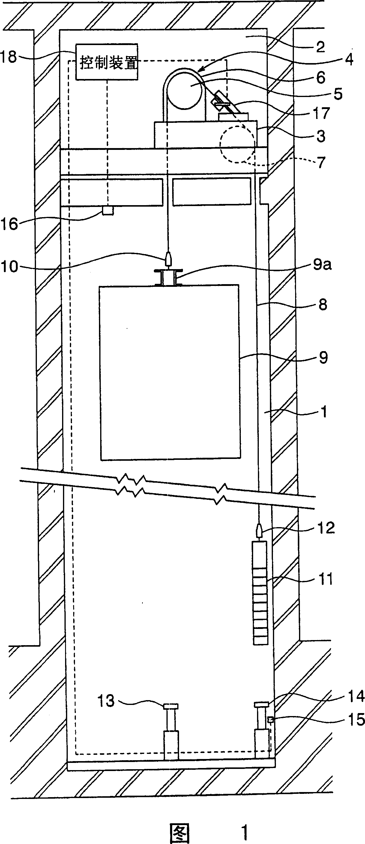
[0016] Figure 1 is a structural diagram showing an elevator apparatus according to Embodiment 1 of the present invention. In the figure, a machine room 2 is arranged above the hoistway 1. A machine table 3 is provided in the machine room 2. The driving device 4 is mounted on the machine table 3. The driving device 4 has a driving pulley 5 and a driving device body 6 that rotates the driving pulley 5. On the machine table 3, a deflection roller 7 that can rotate is mounted with a gap opposite to the drive pulley 5.

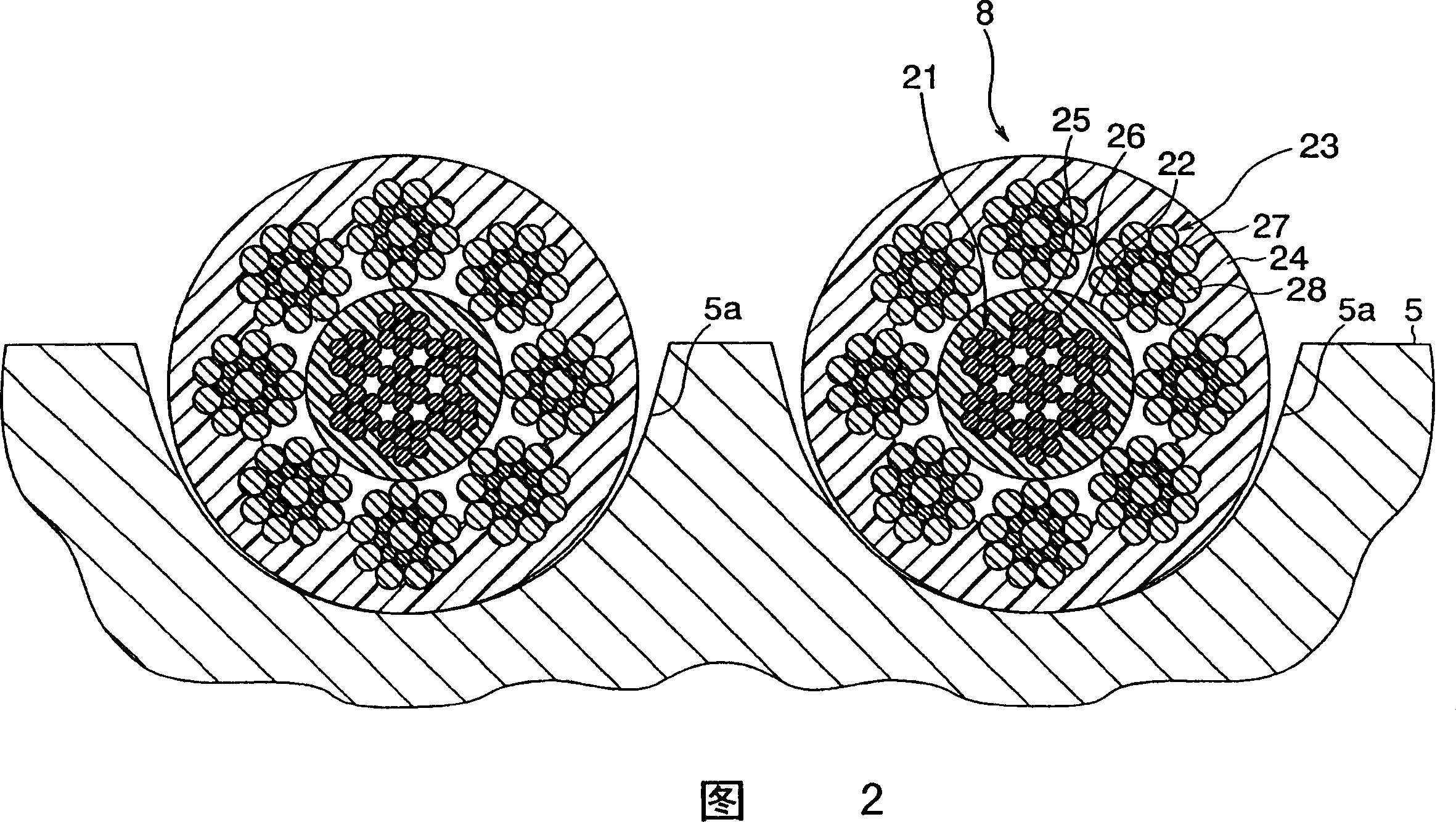
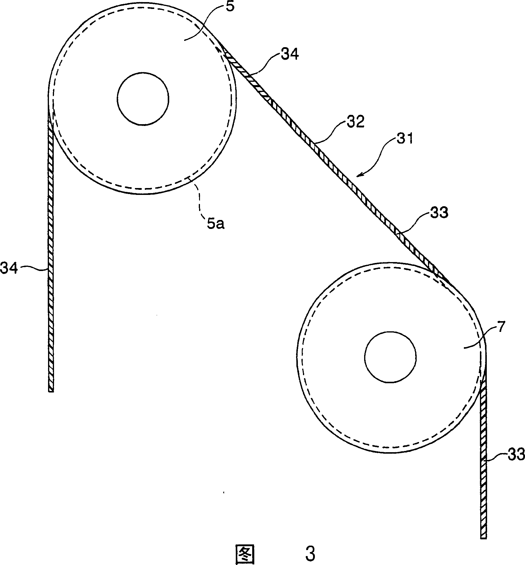
[0017] On the driving pulley 5 and the deflector pulley 7, a plurality of main ropes 8 (only one is shown in FIG. 1) are wound in a semi-hanging (semi-lap) manner. That is, the winding angles of the main rope 8 with respect to the driving pulley 5 and the deflector pulley 7 are respectively less than 180°.

[0018] The car 9 is ...


PUM


Abstract

Elevator equipment, wherein a main rope is wounded on the drive sheave of a drive device, a car and a counterbalance weight are suspended by the main rope, and a rope brake device stopping the rise of the car by the drive device by holding the main rope when the counterbalance weight is moved downward beyond the lower limit of a normal lifting stroke is installed on the counterbalance weight side of the drive sheave.

Description

Technical field [0001] The present invention relates to an elevator device that uses a main rope wound on a driving pulley to lower a car in a hoistway, and uses the traction between the driving pulley and the main rope to lift the car. Background technique [0002] Generally, in an elevator installation, when for some reason the car moves upward beyond the normal lifting stroke, and the counterweight moves downward beyond the normal lifting stroke, the counterweight collides with the buffer at the bottom of the hoistway. stop. When the load of the counterweight is supported by the buffer, the traction on the drive pulley drops sharply. Even if the drive pulley continues to rotate, the drive pulley can slip and idling relative to the main rope. Therefore, when the counterweight collides with the buffer, the lifting of the car is also stopped. [0003] On the other hand, for example, Japanese Patent Laid-Open No. 2001-262482 discloses an elevator device in which the outer circumfe...

Claims


Application Information

Patent Timeline
Patent Type & Authority Patents(China)
IPC IPC(8): B66B5/08B66D5/16B66B5/02
CPCB66B5/185B66B5/02
Inventor 光井厚
Owner MITSUBISHI ELECTRIC CORP
Why Eureka
Try Eureka