Equipment for auxiliary loading of sheet metal cutting machines

A metal plate and cutting machine technology, applied in the field of mechanical processing, can solve problems such as difficulty in feeding materials, and achieve the effects of reasonable structural design, improved convenience, and strong grip

Inactive Publication Date: 2016-12-07
TIANJIN WUQING DISTRICT JINGCHENG METAL PROD
View PDF6 Cites 0 Cited by
  • Summary
  • Abstract
  • Description
  • Claims
  • Application Information

AI Technical Summary

Problems solved by technology

Due to the large quality and width of the sheet metal, it is difficult to load the material onto the processing platform of the cutting machine, so it is particularly important to develop a device suitable for loading large sheet metal

Method used


Image

  • Equipment for auxiliary loading of sheet metal cutting machines
  • Equipment for auxiliary loading of sheet metal cutting machines

Examples


Embodiment Construction

[0010] In order to further understand the content, features, and effects of the present invention, the following examples are given to illustrate in detail as follows:

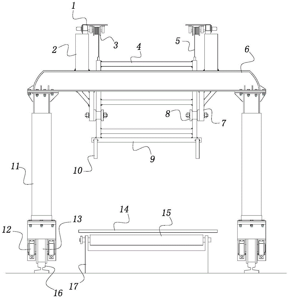
[0011] See figure 1 The present invention includes a floor rail 16 and a frame 17 located between the floor rails 16 and arranged along the length direction. A plurality of supporting shaft rollers 15 of equal height are installed side by side on the top of the frame 17. The metal plate 14 is placed on each supporting shaft roller 15, and the supporting shaft roller 15 rotates under the drive of external force to transport the metal plate 14 forward to a suitable position.

[0012] It also includes four uprights 11 with a driver 12 and a roller 13 installed at the bottom, and the roller 13 is located on the ground rail 16. A crossbeam 6 is installed between the tops of two adjacent uprights 11, four rectangularly distributed bases 2 are fixedly installed on the crossbeam 6, and a reducer 1 is installed on the top o...


PUM


Abstract

The invention belongs to the technical field of mechanical processing and particularly relates to equipment for auxiliary loading of a metal plate cutter. The equipment comprises ground rails and a rack which is positioned between the ground rails and arranged in a length direction, and further comprises four stand columns with drivers and roller wheels on bottoms, and a lifting framework, wherein a plurality of equal-height supporting roller shafts are mounted on the top of the rack in parallel; the roller wheels are positioned on the ground rails; a transverse beam is mounted between tops of the adjacent two stand columns; four bases which are distributed in the form of a rectangle are fixedly connected and mounted on the transverse beams; a speed reducer and a steel cable reel driven by the speed reducer are mounted on the top of each base, and a steel cable is wound on each steel cable reel; the lower end of each steel cable is fixedly connected with the lifting framework; a horizontal bottom framework is fixedly connected and mounted at the bottom end of the lifting framework; a plurality of hangers for hanging a metal plate are arranged on the edge of the bottom framework; left and right groups of wheel racks with limiting roller wheels at bottom ends are fixedly connected on the bottoms of the transverse beams; the edges at the two sides of the lifting framework are blocked between the limiting roller wheels.

Description

Technical field [0001] The invention belongs to the technical field of mechanical processing, and in particular relates to a device for auxiliary feeding of a sheet metal cutting machine. Background technique [0002] In mechanical processing, the processing process using sheet metal as the raw material usually starts with the cutting of the sheet metal, and the above-mentioned cutting process is completed on a sheet cutting machine. Due to the large quality and width of the sheet metal, it is difficult to load materials on the processing platform of the cutting machine. Therefore, it is particularly important to develop a device suitable for feeding large metal sheets. Summary of the invention [0003] In order to solve the technical problems existing in the known technology, the present invention provides an auxiliary feeding device for a sheet metal cutting machine suitable for feeding large metal sheets. [0004] The technical solution adopted by the present invention to solve ...

Claims


Application Information

Patent Timeline
Patent Type & Authority Patents(China)
IPC IPC(8): B23Q7/00B23Q7/05
CPCB23Q7/007B23Q7/05
Inventor 李晓坤刘春江王宝海
Owner TIANJIN WUQING DISTRICT JINGCHENG METAL PROD
Why Eureka
Try Eureka