Novel walking chassis

A walking chassis and chassis technology, which is applied in the field of hybrid power system and new walking chassis, can solve the problems of low fault tolerance rate of equipment and difficult vehicle escape, and achieve high fault tolerance, mature and easy structure, and wide application range

Pending Publication Date: 2021-07-16
HENAN RICHUANG GENERAL MACHINERY MFR
View PDF0 Cites 0 Cited by
  • Summary
  • Abstract
  • Description
  • Claims
  • Application Information

AI Technical Summary

Problems solved by technology

[0003] At present, there have been fully hydraulic drive chassis in China. Most of them use a hydraulic drive pump to drive the differential to drive the wheels to rotate. There are also wheel hub motor drive methods, but these cannot reflect the characteristics of hydraulic direct drive.
At this stage, hydraulic components cannot achieve zero-speed high-power drive very well, and mechanical components are required to decelerate the hydraulic motor at a fixed ratio
In addition, the existing mature products have a low fault tolerance rate for equipment. The engine drives the hydraulic pump, and the hydraulic motor is driven through the hydraulic pipeline. If the main drive pump or related hydraulic components fail, it will make it difficult for the vehicle to get out of trouble and cannot meet people's needs. Therefore, , we propose a new type of walking chassis

Method used


Image

  • Novel walking chassis
  • Novel walking chassis
  • Novel walking chassis

Examples


Embodiment 1

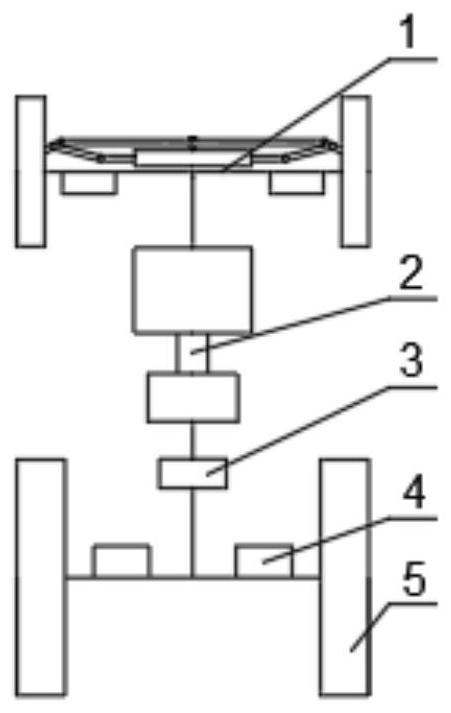
[0026] refer to Figure 1-4 As shown, a new type of walking chassis includes a chassis main body, which is provided with a front axle drive mechanism 1, a chassis power unit 2, a chassis system control unit 3, several groups of independent drive motors 4 and several groups of wheels 5, and the chassis system controls The unit 3 is connected with the front axle driving mechanism 1 , the chassis power unit 2 and the independent drive motor 4 , the chassis power unit 2 is connected with the independent drive motor 4 , and the independent drive motor 4 is connected with the wheels 5 .

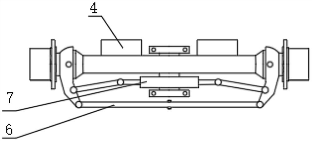
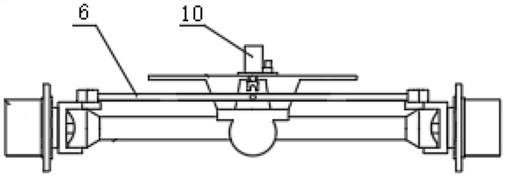
[0027] The front axle driving mechanism 1 includes a fixed seat, a steering tie rod 6, a steering cylinder 7 and a steering center structure that can lock the front axle when the steering is at zero angle. The steering tie rod 6 is installed on the chassis body through the fixing seat, and the steering cylinder 7 Connect with steering rod 6.

[0028] The steering centering structure adopts the nut...

Embodiment 2

[0034] refer to Figure 1-4 As shown, a new type of walking chassis includes a chassis main body, which is provided with a front axle drive mechanism 1, a chassis power unit 2, a chassis system control unit 3, several groups of independent drive motors 4 and several groups of wheels 5, and the chassis system controls The unit 3 is connected with the front axle driving mechanism 1 , the chassis power unit 2 and the independent drive motor 4 , the chassis power unit 2 is connected with the independent drive motor 4 , and the independent drive motor 4 is connected with the wheels 5 .

[0035]The front axle driving mechanism 1 includes a fixed seat, a steering tie rod 6, a steering cylinder 7 and a steering center structure that can lock the front axle when the steering is at zero angle. The steering tie rod 6 is installed on the chassis body through the fixing seat, and the steering cylinder 7 Connect with steering rod 6.

[0036] The steering centering structure adopts the nut ...

Embodiment 3

[0043] refer to Figure 1-4 As shown, a new type of walking chassis includes a chassis main body, which is provided with a front axle drive mechanism 1, a chassis power unit 2, a chassis system control unit 3, several groups of independent drive motors 4 and several groups of wheels 5, and the chassis system controls The unit 3 is connected with the front axle driving mechanism 1 , the chassis power unit 2 and the independent drive motor 4 , the chassis power unit 2 is connected with the independent drive motor 4 , and the independent drive motor 4 is connected with the wheels 5 .

[0044] The front axle driving mechanism 1 includes a fixed seat, a steering tie rod 6, a steering cylinder 7 and a steering center structure that can lock the front axle when the steering is at zero angle. The steering tie rod 6 is installed on the chassis body through the fixing seat, and the steering cylinder 7 Connect with steering rod 6.

[0045] The steering centering structure adopts the nut...


PUM


Abstract

The invention discloses a novel walking chassis which comprises a chassis main body, a front axle driving mechanism, a chassis power device, a chassis system control unit, a plurality of groups of independent driving motors and a plurality of groups of wheels are arranged on the chassis main body, and the chassis system control unit is connected with the front axle driving mechanism, the chassis power device and the independent driving motors. According to the novel walking chassis, enough traction force can be guaranteed; the novel walking chassis has high fault tolerance, after a fault occurs, a vehicle can limp and get out of trouble as long as two driving energy work devices exist, variable steering can be achieved, normal driving comfort is guaranteed, meanwhile, the vehicle can turn in situ, steering wheels are rigidly connected in the in-situ turning process, the wheels on the two sides rotate reversely to achieve in-situ turning in a mode similar to track turning, the design cost can be reduced, machine types can be diversified, large traction force and good control passing performance can be provided for a non-bearing type vehicle body, and better use prospects are achieved.

Description

technical field [0001] The invention relates to the field of vehicle-driven hybrid power, and belongs to a hybrid power system of wheel-side drive and variable steering mode. The utility model is applied to vehicle technology fields such as agricultural machinery and construction machinery, and particularly relates to a new type of walking chassis. Background technique [0002] At present, the vehicle chassis mostly adopts mechanical drive mode, and the engine transmits the power to the gearbox to achieve the purpose of variable speed and torque increase. Due to the different conditions of use, this also limits the fuel economy and operating comfort of the equipment. Hydraulic drive or electric direct drive can better solve the contradiction between engine operating conditions and vehicle operating conditions. Hydraulic drive and motor drive can provide large initial torque and facilitate the realization of continuously variable speed, so they have been developed rapidly. ...

Claims


Application Information

Patent Timeline
Patent Type & Authority Applications(China)
IPC IPC(8): B62D21/00B60B35/12B60K1/00
CPCB60B35/121B60K1/00B62D21/00
Inventor 张玉环陈兰峰方增强岳洪涛
Owner HENAN RICHUANG GENERAL MACHINERY MFR
Why Eureka
Try Eureka