Large reflective mirror fixing device and method of digital light display rear projector

A technology of a fixing device and a fixing method, which is applied to parts of color TVs, parts of TV systems, TVs, etc., can solve problems such as poor operability, difficulty in adjusting optical paths, and broken mirrors, so as to achieve convenient operation and adjustment The effect of large space and increased adjustment speed

Inactive Publication Date: 2008-03-12
SHENZHEN SKYWORTH RGB ELECTRONICS CO LTD
View PDF3 Cites 0 Cited by
  • Summary
  • Abstract
  • Description
  • Claims
  • Application Information

AI Technical Summary

Problems solved by technology

There are two kinds of reflection, primary reflection and secondary reflection. Regardless of primary or secondary reflection, in the actual production process, because of the larger size of the rear projection TV, there is a larger reflector, which is made of glass. , the known large reflector is fixed on the back cover. In this way, during production and debugging, the back cover must be locked on the machine base first to adjust the optical path. However, when adjusting the optical path, a certain amount of operating space is required, but After the back cover is locked, the operating space is limited, making it difficult to adjust the optical path and poor operability
What's more serious is that after the digital light display rear projection is assembled, uninformed people will smash the reflector when they intentionally or unconsciously tap the rear cover

Method used


Image

  • Large reflective mirror fixing device and method of digital light display rear projector

Examples


Embodiment Construction

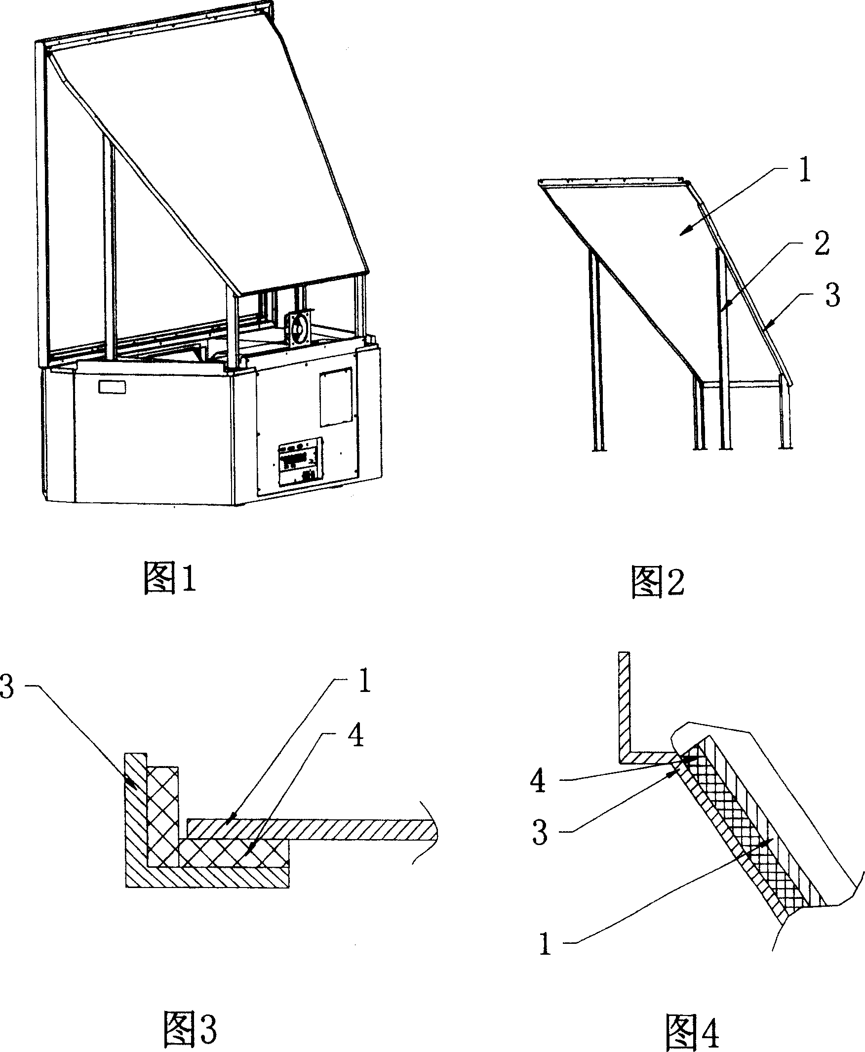
[0023] As shown in Fig. 1, 2, be a preferred embodiment of the present invention, set up four columns from the support, then the metal frame that fixes large reflecting mirror 1 is fixed on the upper end of column, the inclined-plane that metal frame forms and The display screen of the digital light display rear projection is at a certain angle, paste a sponge strip on the frame, and then apply glue, and then install the large reflector 1 on the metal frame facing the display screen, so that the light beam reflected by the large reflector 1 passes through the metal frame. After the optical path is adjusted, it can be displayed on the display screen.

[0024] Figure 3 and Figure 4 show the assembly relationship of the large reflector 1, the metal frame and the sponge strip 4, the shape and size of the metal frame match the shape and size of the large reflector 1, and hold the edge of the large reflector 1, The sponge strip 4 is located between the large reflector 1 and the meta...


PUM


Abstract

This invention relates to a big reflection mirror fixing device of a digital light display back projector and its method including at least three posts stood on the base of the light display back projector with their top fixing the big reflection mirror or two rows of panels, among which, the top of the posts or panels forms a slope in an angle with a display screen of the digital light display projector to fix the mirror facing the screen on the slope formed by top of the posts or panels, which can regulate light paths without mounting back cover to increase the regulation space.

Description

【Technical field】 [0001] The invention relates to a digital light display rear projection, in particular to a fixing device and method for a mirror of LCD, DLP, LcoS and other digital light display rear projections. 【Background technique】 [0002] The basic structure of LCD, DLP, LCOS and other digital light display rear projection is an illumination optical system that directs the light beam emitted by the light source to the liquid crystal light valve, and amplifies the light beam formed by the liquid crystal light valve to form image information, and then reflects it through the mirror. It consists of a projection optical system that projects onto a screen. There are two kinds of reflection, primary reflection and secondary reflection. Regardless of primary or secondary reflection, in the actual production process, because of the larger size of the rear projection TV, there is a larger reflector, which is made of glass. , the known large reflector is fixed on the back co...

Claims


Application Information

Patent Timeline
Patent Type & Authority Patents(China)
IPC IPC(8): H04N5/74
Inventor 古诗路
Owner SHENZHEN SKYWORTH RGB ELECTRONICS CO LTD
Why Eureka
Try Eureka