Cable plug connector

A technology of cable plugs and connectors, applied in the direction of connection, two-part connection devices, circuits, etc., can solve the problems of restricting distribution frames, snap ring elastic failure, inconvenience, etc., achieve convenient installation and maintenance, improve connection efficiency, and improve The effect of electrical properties

Inactive Publication Date: 2008-04-23
宁波吉品科技有限公司
View PDF6 Cites 3 Cited by
  • Summary
  • Abstract
  • Description
  • Claims
  • Application Information

AI Technical Summary

Problems solved by technology

However, in the process of use, it was found that: (1) Since the plug and the socket are connected by threads, they must be screwed many times before they can be installed or disassembled. Obviously, such an operation is time-consuming and laborious, and it is extremely inconvenient, and it is also limited by the operating space. Restrictions, so that each pair of connectors must have a certain distance, and cannot be too close, thus restricting the development of high-density distribution frames to a certain extent
(2) It is also because of the threaded connection method that under the vibration state, it is inevitable that loosening will occur and affect the reliability of the electrical connection between the two
(3) Since the connecting screw sleeve and the shell are connected by an elastic snap ring, and the elastic snap ring is often improperly designed, or the aging treatment temperature is not strictly controlled, it is easy to cause the elasticity of the snap ring to fail, resulting in the connection between the screw sleeve and the shell. phase shedding defect
However, it can be seen from the actual operation process that the threaded connection is still realized by rotating the shell in essence, so the disadvantages caused by the "screwing" action cannot be eliminated.

Method used


Image

  • Cable plug connector
  • Cable plug connector
  • Cable plug connector

Examples


Embodiment Construction

[0018] The present invention will be further described in detail below in conjunction with the accompanying drawings and embodiments.

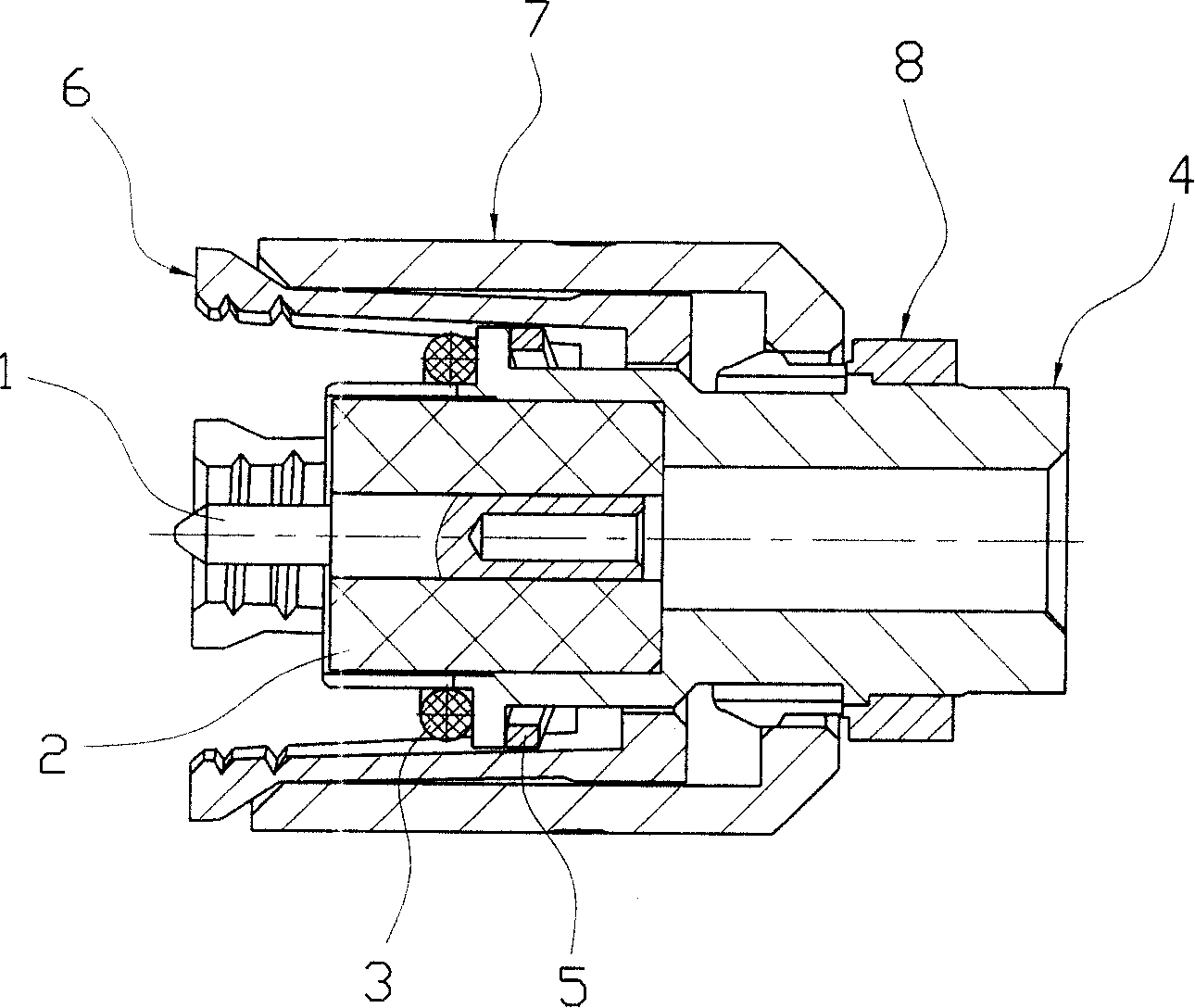
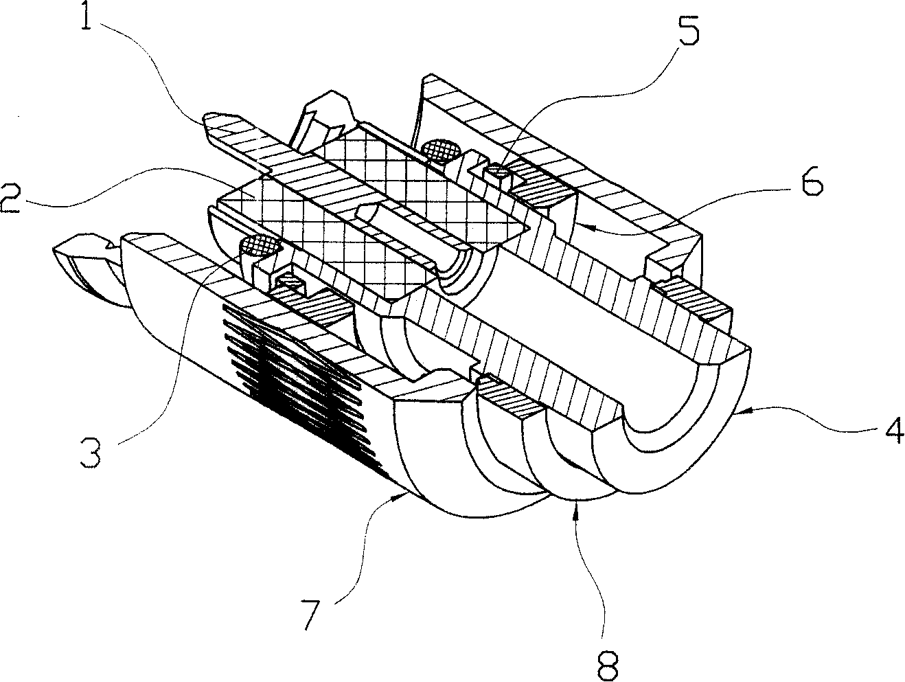
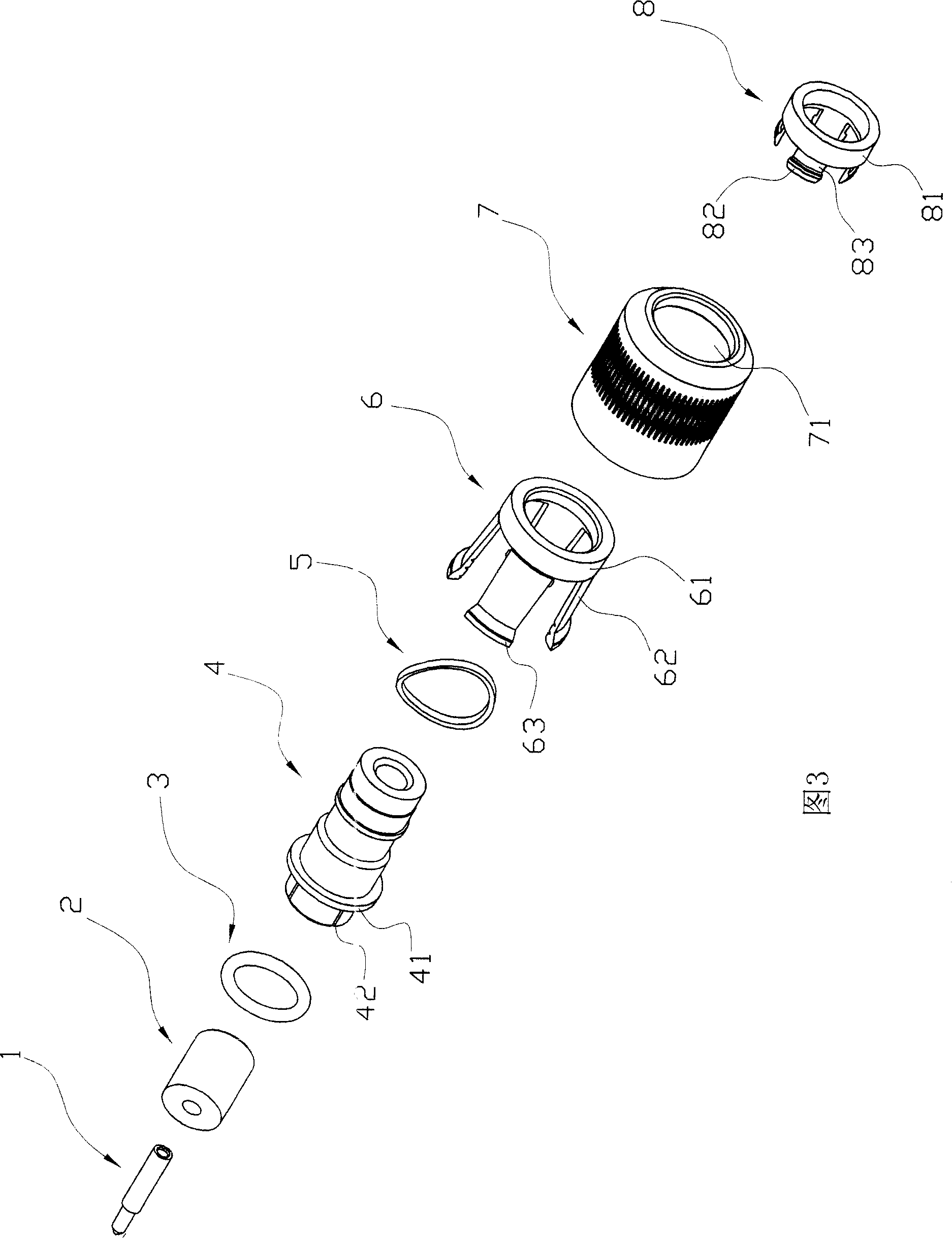
[0019] Such as figure 1 As shown in Figure 3, the structure of the cable plug connector includes a pin 1, an insulator 2, a housing 4, a connecting sleeve 6 and a jacket 7 that are coaxially assembled sequentially from the inside to the outside, wherein the jacket 7 is in the shape of a cylinder, and its opening The place is used for inserting into the socket, and a through hole 71 is provided at the bottom thereof for passing through the shell 4 . And described casing 4 is hollow tubular body shape, and above-mentioned pin 1 and insulator 2 are conventionally installed in the thinner end of its tube wall, and the other end of its tube wall is thicker with coaxial cable (in the figure) (not shown) are fixedly connected, and at the same time, the outer peripheral surface of the housing 4 is provided with an integral shaft shoulder 41 and a st...


PUM


Abstract

The related connector for cable plug comprises: based on original parts, modifying the shell fit to limited move along shaft, arranging a connection sheath between shell and outside sheath that comprises a ring body on shell and some concentric inclined-outside elastic arc pieces extended from ring body to socket opening, the convex edge on arc piece free end gradual transited fit to the inner surface, and the inner thread on inner surface of arc piece free end. This invention overcomes defect of screwing, and can ensure connection reliability.

Description

technical field [0001] The invention relates to a cable plug connector, in particular to a cable coaxial plug connector widely used in radio frequency circuits of microwave equipment and digital communication equipment. Background technique [0002] There are more common cable or microstrip plug connectors (that is, plug male connectors, also referred to as plugs), such as Figure 6 As shown, its structure is assembled with pins, insulators, shells and connecting nuts sequentially from the inside to the outside, wherein, one end of the connecting nut opposite to the cable side has a socket connector for inserting a cable or a microstrip socket (that is, a socket female The opening of the connector (also referred to as the socket) is tapped on the inner peripheral surface of the opening with an internal thread that matches the external thread on the socket, and grooves are respectively provided on the opposite surfaces of the connecting screw sleeve and the shell. An annular ...

Claims


Application Information

Patent Timeline
Patent Type & Authority Patents(China)
IPC IPC(8): H01R24/02H01R13/622H01R24/40
Inventor 曹恺
Owner 宁波吉品科技有限公司
Why Eureka
Try Eureka