Pay-off rack

A technology of pay-off rack and right bracket, applied in the field of pay-off rack, can solve the problems of not restricting the axial movement of the support shaft, detachment of the support shaft, falling off of the support shaft, etc., and achieves a simple structure, uniform force, and reduced friction. Effect

Pending Publication Date: 2018-12-11
HENAN SENYUAN ELECTRIC CO LTD
View PDF6 Cites 3 Cited by
  • Summary
  • Abstract
  • Description
  • Claims
  • Application Information

AI Technical Summary

Problems solved by technology

[0004] But the problem that exists wherein is: when carrying out pay-off work, the cable that is wound on the spool will produce the axial force along the axial direction of support rotating shaft to spool and supporting rotating shaft, and supporting rotating shaft will be under the action of this axial force. Moving along its axial direction, one end ...

Method used


Image

  • Pay-off rack
  • Pay-off rack
  • Pay-off rack

Examples


Embodiment Construction

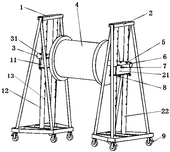
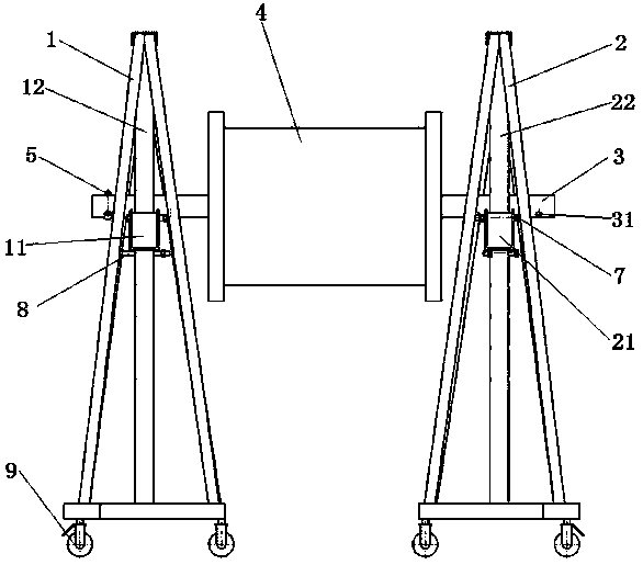
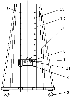
[0026] Such as Figure 1 to Figure 4 As shown, it is a specific embodiment of the pay-off rack in the present invention: the pay-off rack includes two parts, which are respectively the support shaft 3 for the wire drum 4 wound with the cable to pass through, and the support shaft 3 supports the wire drum 4, When it is necessary to pay out the wire, the supporting rotating shaft 3 rotates, which improves the speed of paying out the wire. The pay-off frame also includes a support supporting the rotating shaft 3, and the support is provided with two, respectively, a left support 1 and a right support 2, and a left support seat 11 and a right support are respectively arranged on the left support 1 and the right support 2. The support base 21 , the left support base 11 and the right support base 21 can rotate with the support shaft 3 . In order to reduce the axial movement of the supporting rotating shaft 3 during rotation, so that the supporting rotating shaft 3 will not fall off...


PUM


Abstract

The invention provides a pay-off rack. The pay-off rack comprises a supporting rotating shaft arranged in a bobbin in a penetrating manner and left and right supports used for supporting the supporting rotating shaft. The supporting rotating shaft is provided with a stopping pin which is in stopping fit with the left support and/or the right support along the axial direction of the supporting rotating shaft to limit motion of the supporting rotating shaft. The stopping pin is arranged on the supporting rotating shaft, displacement of the supporting rotating shaft in the axial direction of thesupporting rotating shaft can be limited, and the stopping pin is matched with the two supports to enable the supporting rotating shaft to keep in supporting fit with the supports all the time in therotating process. It can be guaranteed that the supporting rotating shaft cannot fall off from the supports, and therefore the production safety is guaranteed.

Description

technical field [0001] The invention relates to a pay-off frame. Background technique [0002] As a tool that can increase the speed of pay-off and reduce the labor intensity of workers, the pay-off rack is often used in cable laying operations. [0003] The authorized announcement number is CN203903634U, and the patent document whose authorized announcement date is 2014.10.29 discloses a cable pay-off device, including a lifting bar formed by a supporting rotating shaft. The lifting bar is passed through the wire barrel to support the wire barrel. The device is equipped with left and right brackets to support the lifting bar. On the left and right brackets, there are respectively set roller shaft groups that cooperate with the lifting bar. Each roller shaft group includes two roller shafts arranged at intervals, and the distance between them is less than The outer diameter of the lifting bar, when the lifting bar is rotating, the roller shaft can cooperate with the rotatin...

Claims


Application Information

Patent Timeline
IPC IPC(8): B65H49/20
CPCB65H49/20
Inventor 王亚龙魏文勇
Owner HENAN SENYUAN ELECTRIC CO LTD
Why Eureka
Try Eureka