Toroidal and thrust bearing assembly

A bearing assembly and thrust bearing technology, applied in the field of rolling element bearing devices, can solve the problems of rotational inertia limiting operating efficiency, occupying large bearings, high material costs, etc., to improve internal force transmission/distribution and load carrying capacity, compact cross-section , space saving effect

Inactive Publication Date: 2014-11-05
AB SKF
View PDF7 Cites 3 Cited by
  • Summary
  • Abstract
  • Description
  • Claims
  • Application Information

AI Technical Summary

Problems solved by technology

Also, in order to provide sufficient axial load carrying functionality, known solutions involve non-compact designs with large bearings taking up valuable space
Furthermore, designs with large bearing dimensions lead to high material costs and high load capacities, which limit the operating efficiency by, for example, increasing the moment of inertia of the device

Method used


Image

  • Toroidal and thrust bearing assembly
  • Toroidal and thrust bearing assembly
  • Toroidal and thrust bearing assembly

Examples


Embodiment Construction

[0045] In the various figures, similar or identical elements are denoted by the same reference numerals. If not described or otherwise shown, the described embodiments are arranged in a similar or corresponding manner.

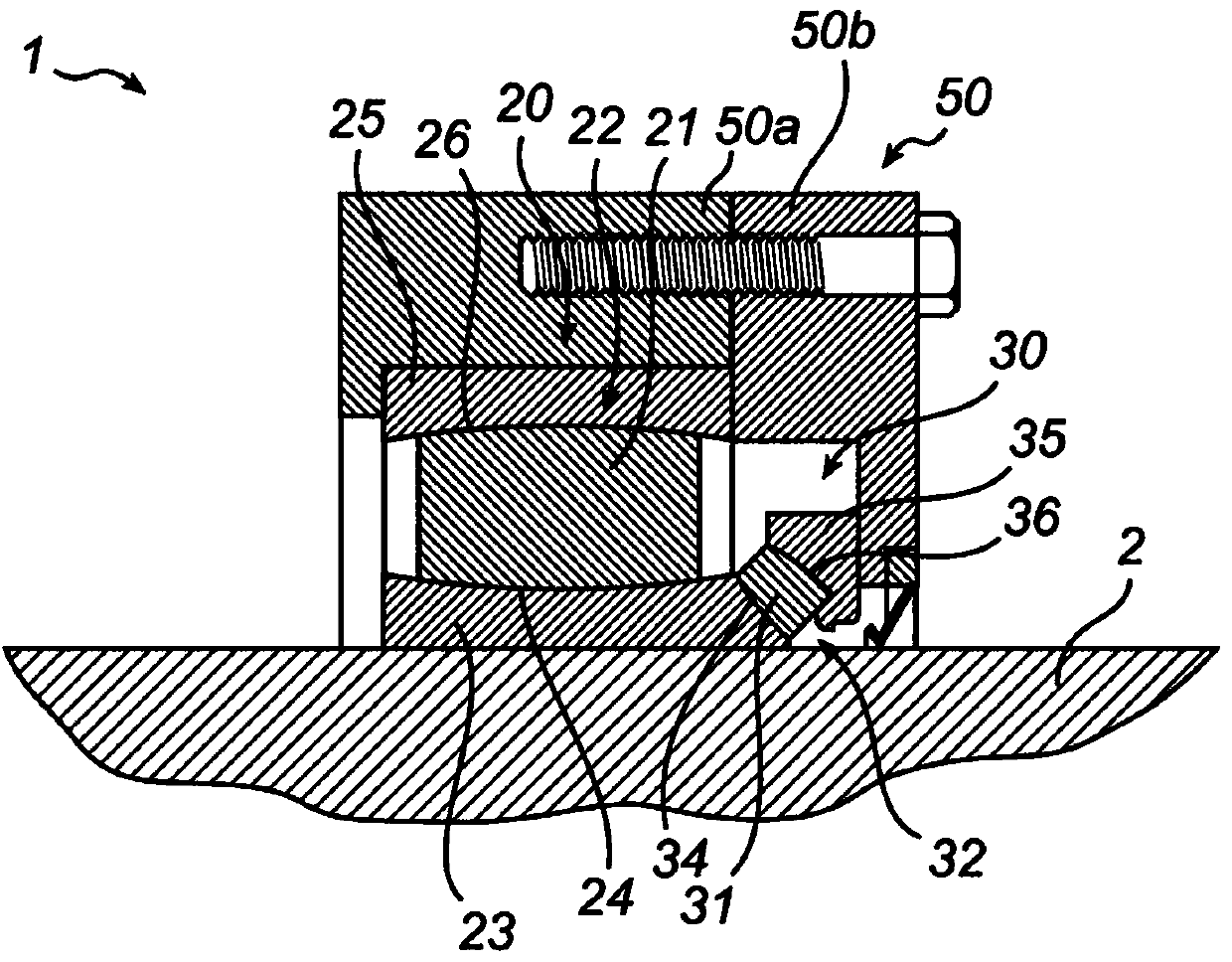
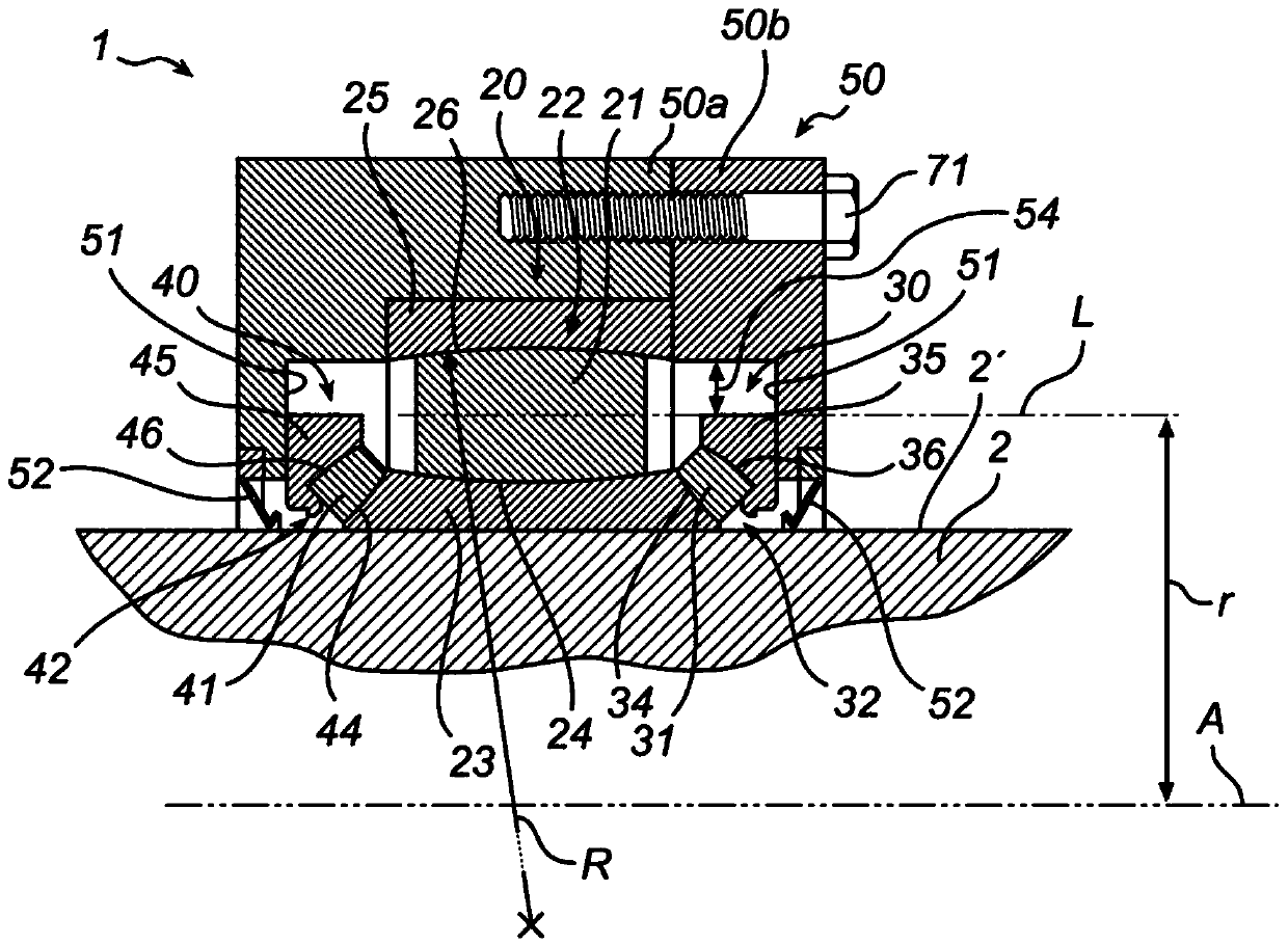
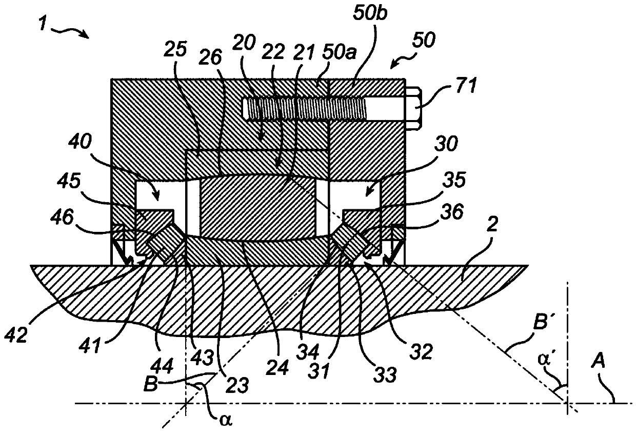
[0046] exist Figure 1-5 , a schematic cross-sectional view of an exemplary embodiment of a bearing assembly 1 for supporting a shaft 2 is shown. The assembly 1 comprises a toroidal roller bearing arrangement 20 comprising a first set of rolling elements formed by toroidal roller elements 21 arranged in a first toroidal circumferential row 22 around the axis of the shaft A and between Between the inner ring 23 including the first inner raceway 24 and the first outer ring 25 including the first outer raceway 26 . The first inner and outer raceways 24, 26 are in contact with the roller elements 21 and are arranged to cooperate with said roller elements, wherein said roller elements roll relative to and against the raceways to allow Axial and angular displacem...


PUM


Abstract

The present invention relates to a bearing assembly (1) for supporting a shaft (2), comprising a toroidal roller bearing arrangement (20) comprising a first set of rolling elements (21) formed of toroidal roller elements, which roller elements are arranged in a first row (22) and interposed between an inner ring (23) comprising a first inner raceway (24) and an first outer ring (25) comprising a first outer raceway (26), and a thrust bearing arrangement (30) comprising a second set of rolling elements (31) arranged in a second row (32), which rolling elements are in contact with and arranged to cooperate with a second inner raceway (34) and a second outer raceway (36) for supporting axial loads and for restricting axial movement of the shaft (2) in relation to the first outer ring (25). The present invention also relates to a method (100) for manufacturing a bearing assembly (1) for supporting a shaft (2).

Description

technical field [0001] The present invention relates to the field of rolling element bearing arrangements, and more particularly to a bearing assembly for supporting and axially locating a rotating shaft, such as a wind turbine rotor shaft, which assembly includes a combination of at least partially unconstrained axial bearings allowing self-aligning capabilities. Displacement toroidal roller bearing units and thrust bearing units. [0002] The invention also relates to a method of manufacturing a bearing assembly for supporting a shaft, the assembly comprising an annular bearing arrangement. Background technique [0003] In high torque transmitting and high load applications involving rotating shafts in space-constrained housings, such as the rotor shaft of a wind turbine, the rotating shaft is typically supported by spherical roller bearings having a spherical geometry that allows the shaft to self-align during operation. By self-aligning, the angular alignment of the axi...

Claims


Application Information

Patent Timeline
Patent Type & Authority Applications(China)
IPC IPC(8): F16C23/08F03D11/00F16C19/38F41A27/08
CPCF03D11/0008Y02E10/722F16C19/383F16C23/082F16C19/381F16C19/49F16C19/56F16C23/08F16C35/042F16C35/077F16C43/06F16C2300/14F16C2360/31F03D80/70Y02E10/72Y02P70/50
Inventor C.臧
Owner AB SKF
Why Eureka
Try Eureka