
Linear roller bearing provided with a sensor for determining displacement resistance

A sensor, linear technology, applied in the direction of linear motion bearing, bearing, bearing assembly, etc., can solve the problem of not monitoring the formation of pitting corrosion or undesired entry of dirt, and achieve the effect of preventing production downtime

Inactive Publication Date: 2008-04-30
SCHAEFFLER TECH AG & CO KG
View PDF6 Cites 2 Cited by
  • Summary
  • Abstract
  • Description
  • Claims
  • Application Information

AI Technical Summary

Problems solved by technology

However, the formation of pitting or the ingress of undesired dirt is not monitored in such linear bearing components

Method used


Image

  • Linear roller bearing provided with a sensor for determining displacement resistance
  • Linear roller bearing provided with a sensor for determining displacement resistance
  • Linear roller bearing provided with a sensor for determining displacement resistance

Examples


Embodiment Construction

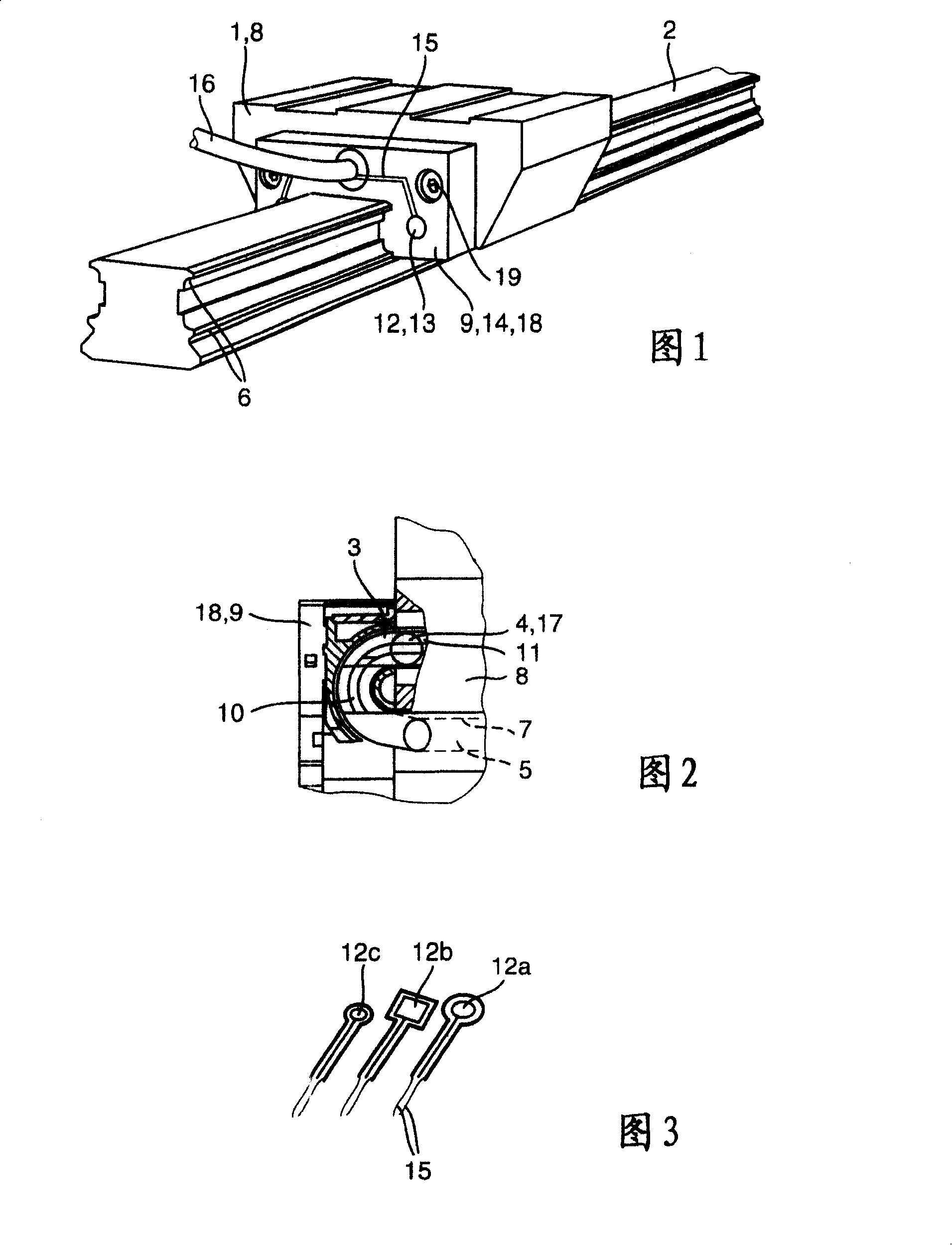
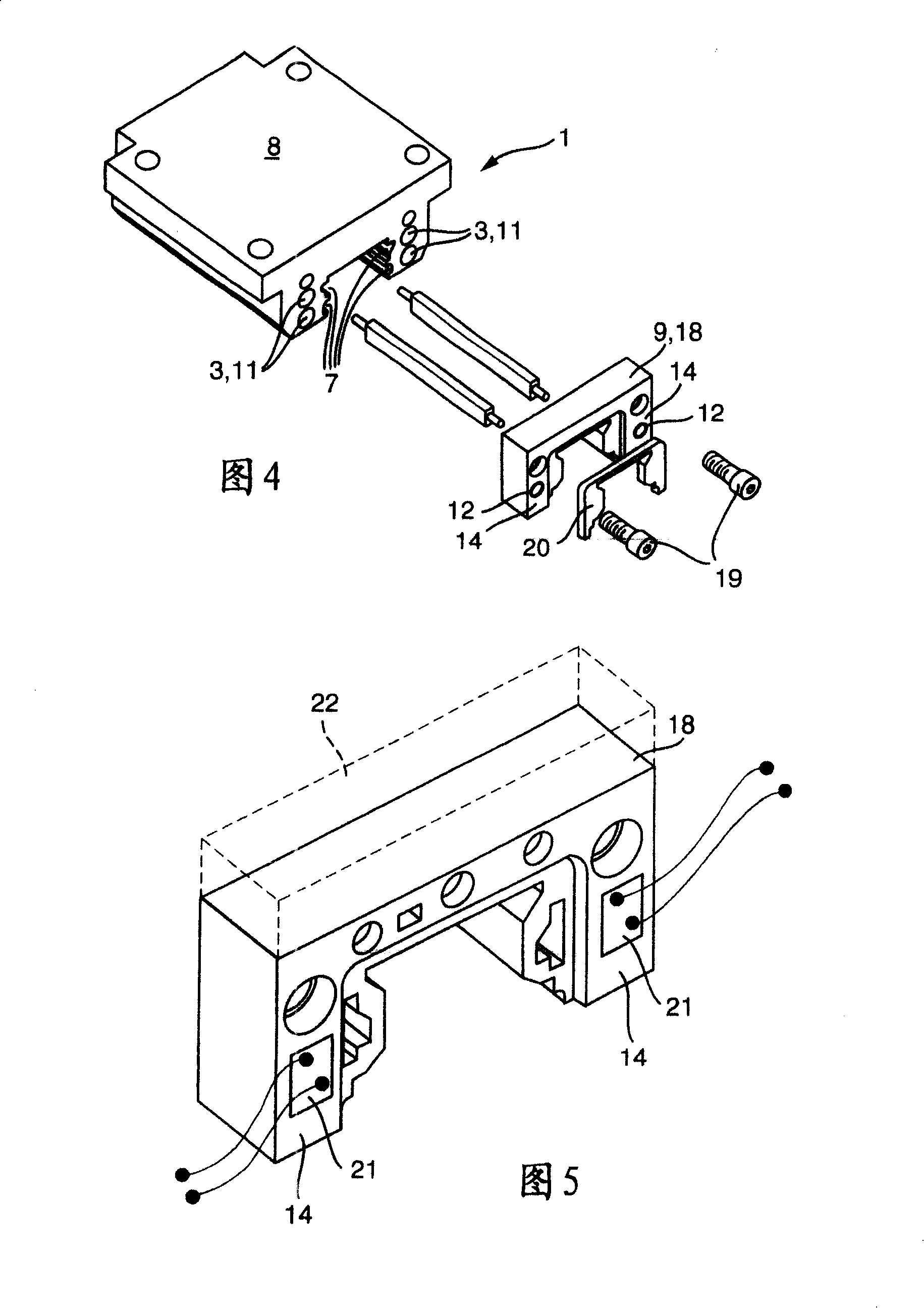
[0029] The linear rolling bearing shown in FIGS. 1-4 has a carriage 1 which is mounted rolling on a guide rail 2 . The carriage 1 comprises two continuous rolling body channels 3 for rolling bodies 4 on both longitudinal sides of the guide rail 2 , one of which is shown in FIG. 2 . Each rolling body channel 3 includes a bearing channel 5 for a loaded rolling body 4 . In the bearing channel 5 the rolling bodies 4 roll on raceways 6 , 7 , of which one raceway 6 is formed on the guide rail 2 and the other raceway 7 is formed on the bearing body 8 of the carriage 1 .

[0030] An end section 9 is provided on both end faces of the carrier body 8 , in which a deflection channel 10 is formed. The rolling body channel 3 also includes a return channel 11 , which is formed on the bearing body 8 . The two deflection channels 10 connect the bearing channel 5 via a return channel 11 to the continuous rolling body channel 3 in which the rolling bodies 4 circulate continuously.

[0031] Th...


PUM


Abstract

The invention relates to a linear roller bearing provided with a guide carriage (1) which can be mounted on a guide rail (2) in a rolling manner by means of roller bearings (4). Said guide carriage is provided with at least one continuous roller bearing channel (3) for the roller bearings (4). The roller bearing channel (3) comprises a support channel (5) for supporting the roller bearings (4), a return channel (11) for returning the roller bearings (4), and deflecting channels (10) which connect the support channel (5) to the return channel (11). The deflecting channels (10) are provided on the end elements (9) of the guide carriage (1), and the roller bearings (4) in the roller bearing channel (3) are subject to displacement resistance in the direction of rotation. The end elements (9) are respectively provided with a sensor (12), whereby the preferably electrical signal thereof is dependent on the displacement resistance.

Description

technical field [0001] The invention relates to a linear rolling bearing. Such linear rolling bearings are used, for example, in machine tools, but also in equipment machines or in general processing lines. In this way, machine components can be guided in the longitudinal direction without problems and with high precision. Background technique [0002] A linear rolling bearing is known, for example, from EP-0558761 B1, which has a carriage which is mounted rollingly on a guide rail via balls and which is provided with a plurality of continuous ball channels for the balls. Each ball channel includes a bearing channel for carrying balls that roll on the raceways of the guide rail and carriage. Each ball channel also includes a return channel in which the balls return unloaded. Furthermore, the ball channel comprises two deflection channels which continuously connect the bearing channel with the return channel. These deflection channels are formed on the end sections of the...

Claims


Application Information

Patent Timeline
Patent Type & Authority Patents(China)
IPC IPC(8): B23Q1/25F16C29/04F16C29/00F16C29/06F16C33/66F16C41/00
CPCF16C29/0609F16C29/0633F16C41/00F16C33/6622F16C33/6674F16C33/667
Inventor D·鲁迪P·卢茨M·门格斯
Owner SCHAEFFLER TECH AG & CO KG
Learn More