
System for mine safety monitoring and disaster emergency communication and method for operating the same

A security monitoring and emergency communication technology, applied in the field of sensing technology and wired and wireless communication, can solve the problems of positioning, tracking and communication function failure, single function, and no trapped personnel included.

Inactive Publication Date: 2008-06-04
HEFEI INSTITUTES OF PHYSICAL SCIENCE - CHINESE ACAD OF SCI
View PDF4 Cites 2 Cited by
  • Summary
  • Abstract
  • Description
  • Claims
  • Application Information

AI Technical Summary

Problems solved by technology

At this time, the underground wired network in the mine is very fragile, and the communication is easily interrupted; once interrupted, the trapped personnel cannot get in touch with the command center, and the positioning, tracking and communication functions will immediately fail
Therefore, the defects of the above-mentioned wired communication network in mine disaster rescue are obvious
[0010] Secondly, the emergency rescue communication system that is currently put into practical use is limited to the deployment between the ground command center-underground command center-rescue team, and does not include the trapped people who most need communication rescue, so they cannot communicate with the outside world, and the outside world also cannot communicate. There is no way of knowing their location and environmental conditions
[0011] Thirdly, the current mine environment operation monitoring system has a single function, fails to realize the organic combination of multiple functions, and does not give full play to the advantages of underground wireless communication
For example, in the commonly used mine safety monitoring system, only a limited number of gas sensors are arranged, and the arrangement of gas sensors on the mining face often cannot keep up with the speed of mining advancement, resulting in a large number of dead spots for environmental detection

Method used


Image

  • System for mine safety monitoring and disaster emergency communication and method for operating the same
  • System for mine safety monitoring and disaster emergency communication and method for operating the same

Examples


Embodiment Construction

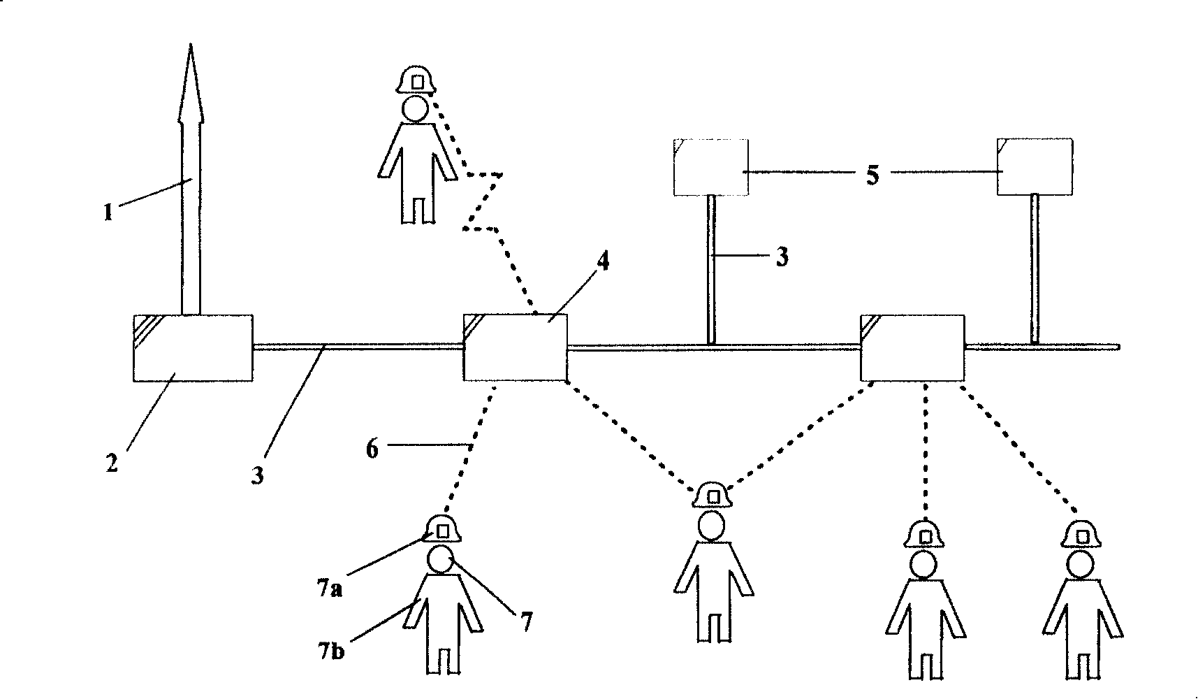
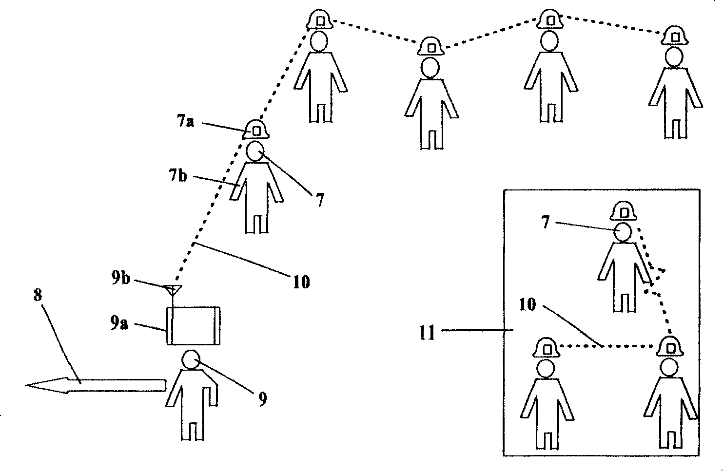
[0032] see figure 1 , figure 2 , the wired backbone network access 1 is electrically connected to the wireless device access point 4 via the gateway device 2 and the field bus 3, and the wireless device access point 4 is electrically connected to a plurality of mobile wireless sensor nodes 7 via a radio frequency communication link 6, wherein , the mobile wireless sensor node 7 is equipped with a wireless sensor communication device 7a, which are all carried by the underground miner 7b, and the field bus measurement and control device 5 is electrically connected with the wireless device access point 4 via the field bus 3 to form a network system for mine safety monitoring structure. The mobile wireless search device 9a with the transceiver antenna 9b is placed at the underground rescue personnel 9, and is carried by the underground rescue personnel 9. The wireless sensor communication device 7a and the rescue command center 8 on the well pass through the mobile wireless sear...


PUM


Abstract

This invention relates to a mine safety monitoring and disaster emergency communication system, in addition to an operating method. Said system comprises the electric connected stamina network switch-in, gateway apparatus, on-site bus, wireless device switch-in, and the wired network system which comprises on-site bus monitoring device and which is electric connected with the on-site bus; several mobile wireless senor junctions are electric connected with the wireless device switch-in of the wired network system through the wireless radio-frequency communication link circuit; it has a wireless sensor communication device in the mobile wireless sensor junction . The method comprises two modes; when mine working normally, the net is safety monitoring mode, and the wireless sensor node will provides orientation, tracing and communication function as a moving object; when urgency disaster happens, the wired communication mode become invalid, and the wireless sensor junction will open self-organization to form emergency communication mode.

Description

technical field [0001] The invention belongs to the field of sensing technology and wired and wireless communication, and in particular relates to mine safety monitoring and disaster emergency communication systems and operating methods for coal mines, metal mines and oil and gas wells. Background technique [0002] Coal mines, metal mines, oil and gas mines and other resource mining industries are the industries with the most frequent and serious casualties in my country's industrial production today. Especially in coal mine mining, the number of deaths per million tons of coal is much higher than that of major foreign coal producers. country. The negative impact of the mine disaster has far exceeded the economic scope. It has caused the victims to suffer tremendous physical and mental pain, and the image of the enterprise and the government has been greatly damaged. environmental hazards, becoming one of the potential social disharmony and instability factors. [0003] In...

Claims


Application Information

Patent Timeline
IPC IPC(8): E21F17/18H04B7/00H04L12/00
Inventor 马祖长孙怡宁梅涛王锐马以武周旭杨新刚蔡林沁黄健丁力徐姝
Owner HEFEI INSTITUTES OF PHYSICAL SCIENCE - CHINESE ACAD OF SCI
Learn More