High pressure valve

A high-pressure valve and valve body technology, which is applied in the direction of sliding valves, valve devices, engine components, etc., can solve problems affecting valve sealing performance, cavitation or abrasion, and seal failure, so as to increase the failure rate, reduce maintenance costs, cost-saving effect

Active Publication Date: 2008-06-04
营口埃斯威特阀门有限公司
7 Cites 0 Cited by

AI-Extracted Technical Summary

Problems solved by technology

[0007] For the above-mentioned several existing valves, the contact surface often causes cavitation or scratches due to the entry of gas and foreign matter during opening and closing, resulting in seal fai...

Method used

As shown in accompanying drawing 2,3,4, a kind of high pressure valve of the present invention, it mainly comprises the valve body 2 that is connected with the pipeline that fluid horizontal direction flows, and above-mentioned valve body 2 and valve plate 16,18 are housed After side bonnet 10,12 is connected, it forms accommodating space in it, is provided with spool cover 30 in accommodating space, is provided with spool 32,34 in the spool hole of spool cover 30 two ends, and spool 32,34 is connected with respectively The springs S1 and S2 are pressed into the spool hole together, the spools 32, 34 are in contact with the sliding sealing surfaces 24 of the flow distribution plates 16, 18, the spool sleeve 30 can be raised and lowered in the accommodation space, and the lower part of the valve stem 36 is connected to the spool sleeve 30. The upper part is connected to the driving device 14, and the driving device 14 makes the valve core sleeve 30 slide up and down with the sliding sealing surface through the valve stem 36, and forms a switch between the fluid inlet and the two side shunt channels connected with it, as shown in Figure 5 As shown, the valve rod 36 is an integral connecting rod, which ensures its durability. The sleeve body of the valve core sleeve 30 is provided with a flow hole communicating with the insid...

Abstract

The invention relates to high pressure valve. It includes valve body and setting space formed by valve body, port plate, and side valve cover. Its features are as follows: the setting space is set valve core cover, valve core, and spring; the two ends of the cover are set valve core hole; and the cover body is set through flow hole. And it can be formed switch to realize valve bar safe force balance and sealed self compensation. This not only can increase valve response speed, but also can improve sealing performance.

Application Domain

Slide valve

Technology Topic

EngineeringHigh pressure +3

Image

  • High pressure valve
  • High pressure valve
  • High pressure valve

Examples

  • Experimental program(1)

Example Embodiment

[0028] Example 1:
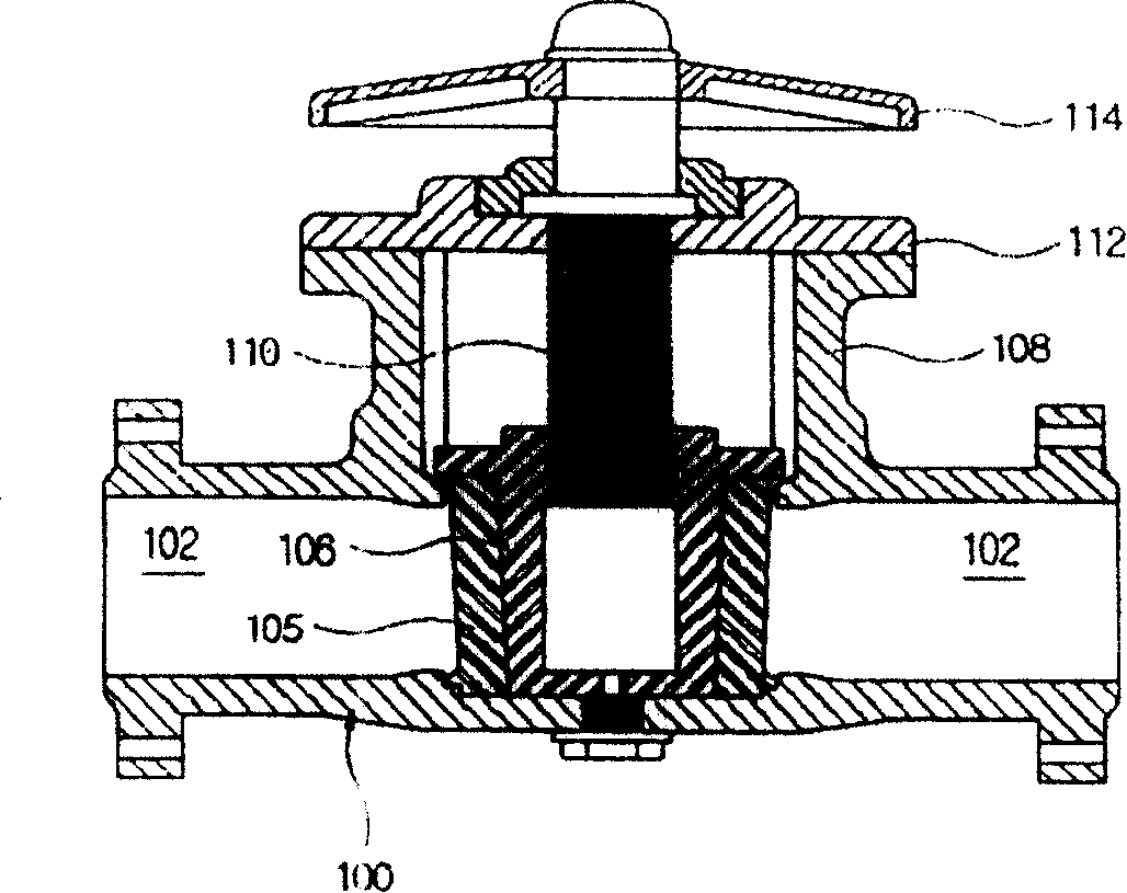
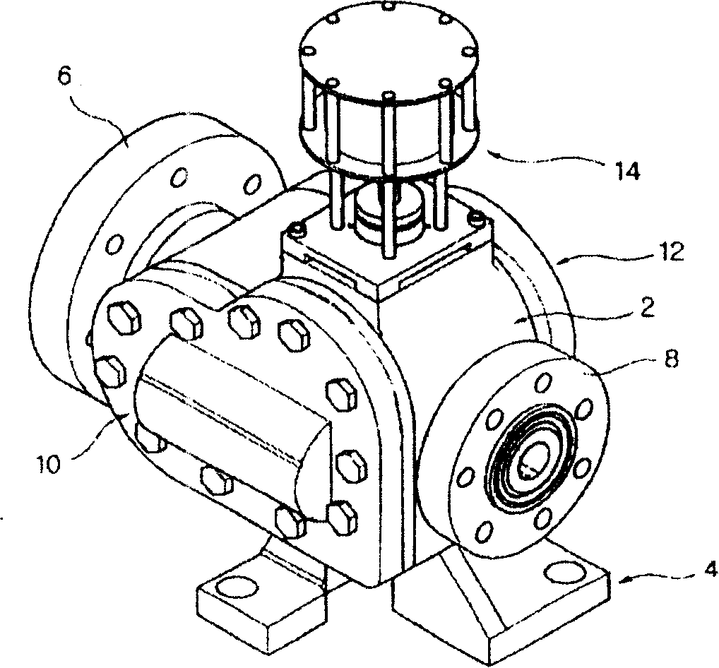
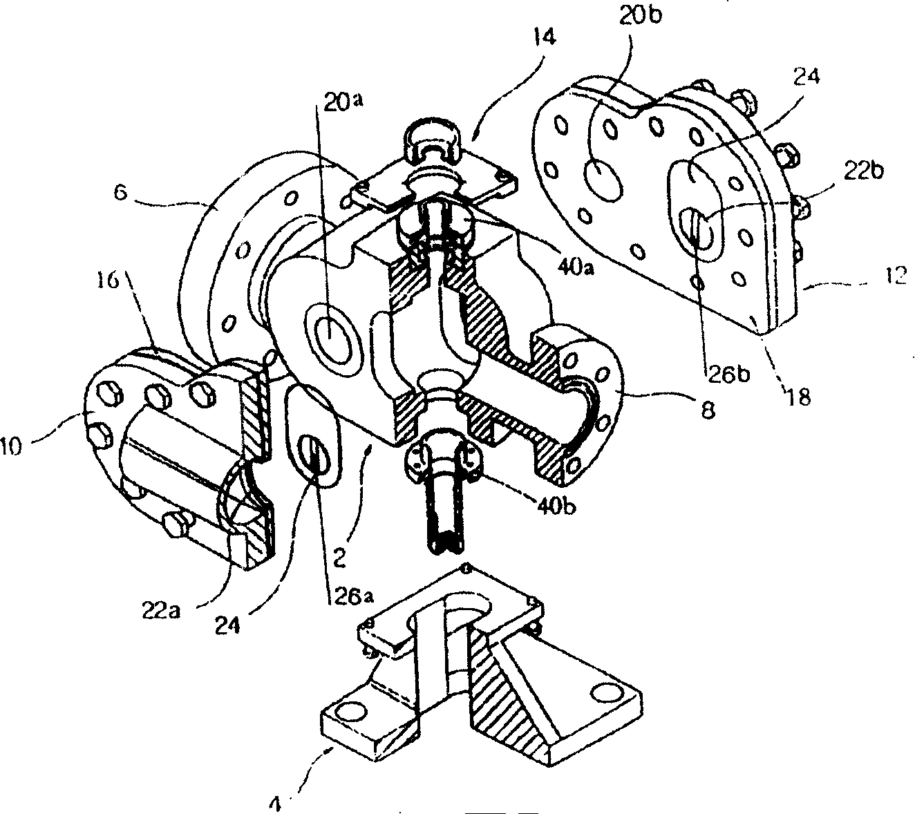
[0029] As attached figure 2 , 3 As shown in Figure 4, a high-pressure valve of the present invention mainly includes a valve body 2 connected to a pipeline through which fluid flows in the horizontal direction. The valve body 2 is connected to the side valve covers 10 and 12 equipped with the valve plates 16, 18 An accommodating space is formed in the accommodating space, and the spool sleeve 30 is arranged in the accommodating space. The spools 32 and 34 are arranged in the spool holes at both ends of the spool sleeve 30. The spools 32 and 34 are pressed into the spool together with the springs S1 and S2 respectively. In the hole, the valve cores 32 and 34 are in contact with the sliding sealing surfaces 24 of the valve plates 16, 18, and the valve core sleeve 30 can be raised and lowered in the containing space. The lower part of the valve stem 36 is connected to the valve core sleeve 30 and the upper part is connected to the driving device 14 to drive The device 14 slides the valve core sleeve 30 and the sliding sealing surface up and down through the valve stem 36, forming a switch between the fluid inlet and the two side flow paths communicating with it, such as Figure 5 As shown, the valve stem 36 is an integral connecting rod to ensure its durability. The sleeve body of the valve core sleeve 30 is provided with a through hole communicating with the inside of the valve core holes at both ends, and the sleeve body of the valve core sleeve 30 It is set directly opposite to the fluid inlet of the valve body. The sleeve body of the valve core sleeve 30 is provided with a through hole facing the fluid inlet. The through hole is provided with four pipelines in the radial direction of the sleeve body and two pipes in the axial direction. Each two radial pipelines are connected to one axial pipeline. Both ends of the two axial pipelines are connected to the valve core holes at both ends of the valve core sleeve 30. The valve cores on both sides of the valve core sleeve 30 32 and 34 are in contact with the outlets of the branch flow paths on both sides of the valve body 2. After the valve is closed, the dual action of the high-pressure fluid flowing in through the flow hole and the spring force makes the two valve cores always in close contact with the fluid outlet at the sliding sealing surface, realizing the sealing self-compensation effect. The sliding sealing surface 24 is provided with a guide belt 26b that facilitates the sliding and lifting of the valve core sleeve 30 and the valve cores 32 and 34 at both ends. Solid lubricants are provided on the sliding sealing surfaces in contact with the valve cores 32 and 34 to ensure that no dry friction occurs.
[0030] That is, the flanges 6 and 8 on both sides of the valve body 2 are the inlet and outlet of the fluid, and form an accommodation space with the side valve covers 10 and 12 equipped with the valve plate 16, 18, and the sliding sealing surface in the accommodation space The orifices are the orifices 22a and 22b. The valve core sleeve 30 can rise and fall in the accommodating space to form the valve cores 32 and 34 in the two ends of the valve core sleeve 30. The pairs of orifices 22a and 22b on the sliding sealing surface 24 are formed. On and off.
[0031] As mentioned above, the guide belts 26a, 26b on the distribution ports 22a, 22b on the valve plates 16, 18 act as a guide when the valve cores 32, 34 rise and fall.
[0032] In addition, the valve core sleeve 30 can be driven by a driving device with the same function as the electromagnet on the solenoid valve. In this way, the valve cores 32 and 34 on the valve core sleeve 30 can selectively open and close the diversion ports 22a and 22b.
[0033] Moreover, in the accommodating space of the valve body 2, the upper central part of the valve core sleeve 30 and the valve core sleeve perpendicularly connect the driving device 14 to the connecting part of the valve stem 36. The lower part of the valve stem 36 penetrates the valve core sleeve 30 into the guide of the lower part of the valve body 2. In the hole.
[0034] The above-mentioned guide hole is provided in the lower valve cover 40b. The lower valve cover 40b is connected to the lower part of the valve body 2 and is arranged in the central hole of the bracket 4. The lower end of the guide hole is a closed structure, and the bracket 4 is connected to the lower part of the valve body 2.
[0035] The valve body 2 is composed of valve plates 16, 18, side valve covers 10, 12, stop valve cover 40a, and lower valve cover 40b.
[0036] That is, the above-mentioned fluid flows from the inlet to the branch ports 22a, 22b of the accommodating space of the valve body, passes through the fluid passages on both sides to the collection ports 20a, 20b, and then flows out of the outlet.
[0037] As mentioned above, springs S are provided in the valve core holes at both ends of the valve core sleeve 30 1 , S2 , And press into the valve cores 32, 34, so that the valve core sleeve 30, the valve cores 32, 34 and the spring form a valve core hole space. The through hole on the outer circle of the valve core sleeve communicates with the valve core hole, and the valve cores 32 and 34 are pressed against the sliding sealing surface 24 by spring force and fluid pressure.
[0038] That is, the present invention drives the valve stem 36 to raise and lower the valve core sleeve 30 by the driving force of the driving device 14. The valve cores 32 and 34 at the two ends of the valve core sleeve 30 form switches for the diversion ports 22a and 22b on the sliding sealing surface, and pass the fluid passages on both sides to the collection ports 20a and 20b to control the on and off of the high pressure fluid flow.
[0039] When the valve core sleeve 30 rises along the sliding sealing surface 24 to expose the shunting ports 22a, 22b, high-pressure fluid flows in and out through the pipeline connected with the flange. On the contrary, when the valve core sleeve 30 descends along the sliding sealing surface 24 and the valve cores 32, 34 cover the diversion ports 22a, 22b, the high-pressure fluid of the pipeline connected by the flanges 6, 8 is cut off.
[0040] The beneficial effects provided by the present invention are that under the high-pressure fluid state, the response speed of the valve is improved, the sealing performance is greatly improved, and the water hammer phenomenon can be prevented.
[0041] The present invention can be used as a descaling valve in hot rolling descaling in the iron and steel industry to control the descaling high-pressure water, and can prevent water hammer from occurring when the high-pressure water is instantly closed. When the valve core 32, 34 When wear occurs, the springs s1 and s2 in the valve core sleeve 30 and the high-pressure fluid introduced into the valve core holes at both ends of the valve core sleeve 30 make the worn valve core sleeves lean against the sliding sealing surface, forming an automatic compensation for valve core wear. .
[0042] The invention can easily control the opening and closing of the valve with a small driving force when controlling the on and off of the high-pressure fluid, and has a good sealing effect.
[0043] The experiment report when the high-pressure valve of the present invention is used as a descaling valve is submitted as an attachment for the actual examination, and it can reflect that its life and durability are greatly improved.

PUM

no PUM

Description & Claims & Application Information

We can also present the details of the Description, Claims and Application information to help users get a comprehensive understanding of the technical details of the patent, such as background art, summary of invention, brief description of drawings, description of embodiments, and other original content. On the other hand, users can also determine the specific scope of protection of the technology through the list of claims; as well as understand the changes in the life cycle of the technology with the presentation of the patent timeline. Login to view more.

Similar technology patents

Fluorescent silver cluster, and preparation method and application thereof

Owner:SUZHOU INST OF NANO TECH & NANO BIONICS CHINESE ACEDEMY OF SCI

Preparation method of paper reinforcing agent

ActiveCN107141409Agood stabilityIncrease the copolymerization rate
Owner:GUANGDONG PAPER IND RES INST

Automatic focusing method and automatic focusing device

ActiveCN104102068Afast focusinggood stability
Owner:ALTEK SEMICON

Classification and recommendation of technical efficacy words

  • good stability
  • High failure rate

Method for controlling pulley homing in optic disc machine

InactiveCN1649015AHigh failure rate
Owner:LITE ON IT

Cooling system for power electronic equipment

ActiveCN113137771AHigh failure rate
Owner:CSR ZHUZHOU ELECTRIC LOCOMOTIVE RES INST
Why Eureka
Try Eureka