Top comb and top comb holder for a textile combing machine, and the combing machine

A combing machine and top combing technology, which is applied in the direction of combing machines, textiles, papermaking, fiber processing, etc., can solve problems such as wear and tear, and achieve the effect of reducing wear and reducing surface pressure

Inactive Publication Date: 2008-07-02
STAEDTLER & UHL
View PDF7 Cites 2 Cited by
  • Summary
  • Abstract
  • Description
  • Claims
  • Application Information

AI Technical Summary

Problems solved by technology

This leads to point or linear loads between the fixed segment and the clip, which cause a lot of wear

Method used


Image

  • Top comb and top comb holder for a textile combing machine, and the combing machine
  • Top comb and top comb holder for a textile combing machine, and the combing machine
  • Top comb and top comb holder for a textile combing machine, and the combing machine

Examples


Embodiment Construction

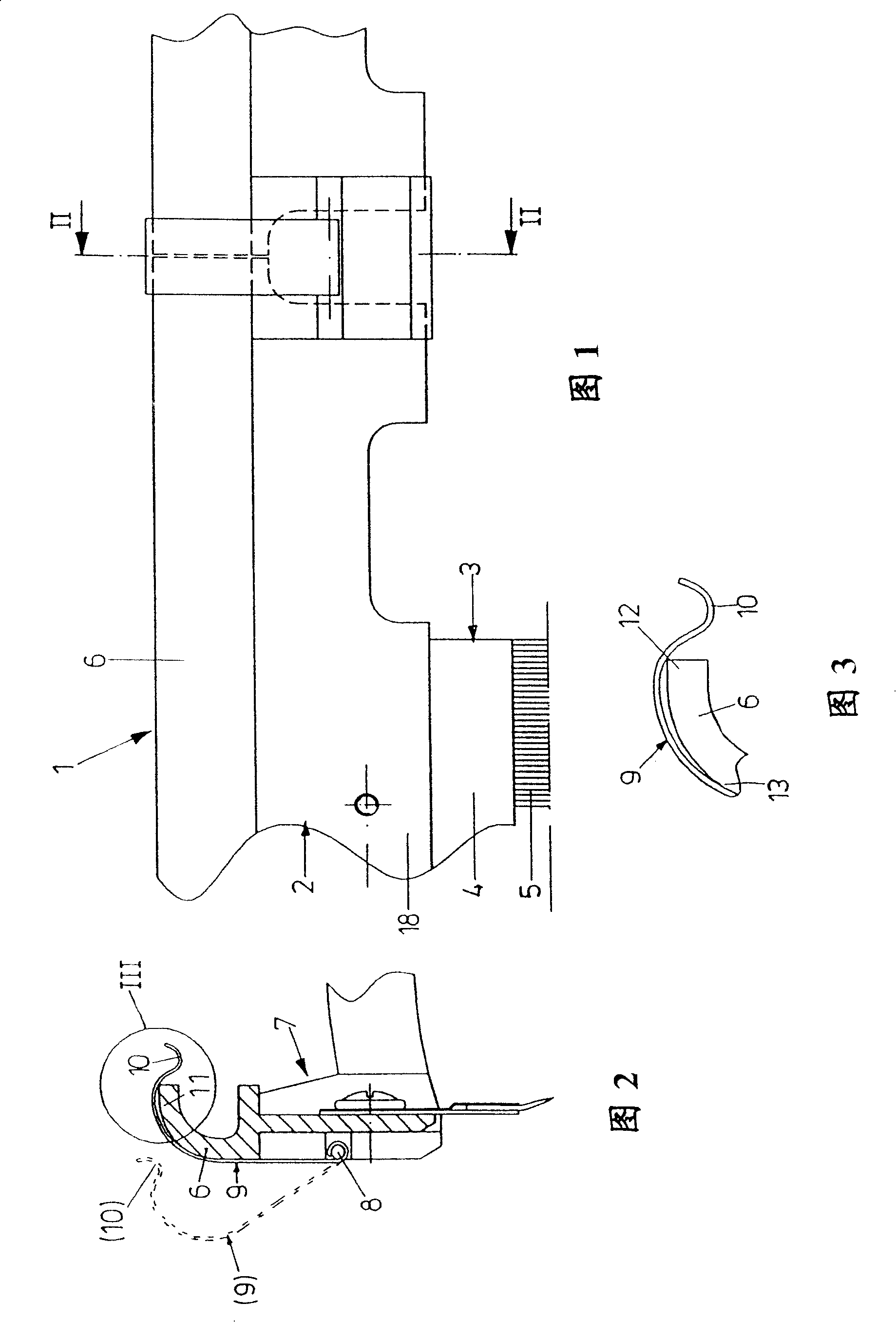
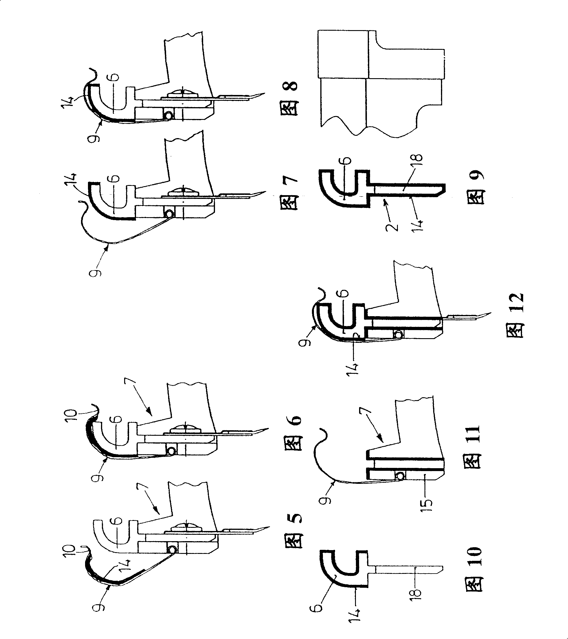
[0030] FIG. 1 shows a top comb 1 according to the prior art, which comprises a top comb plate 2 on which a needle bar 3 with a row of needles 5 clamped between two cover plates 4 is located.

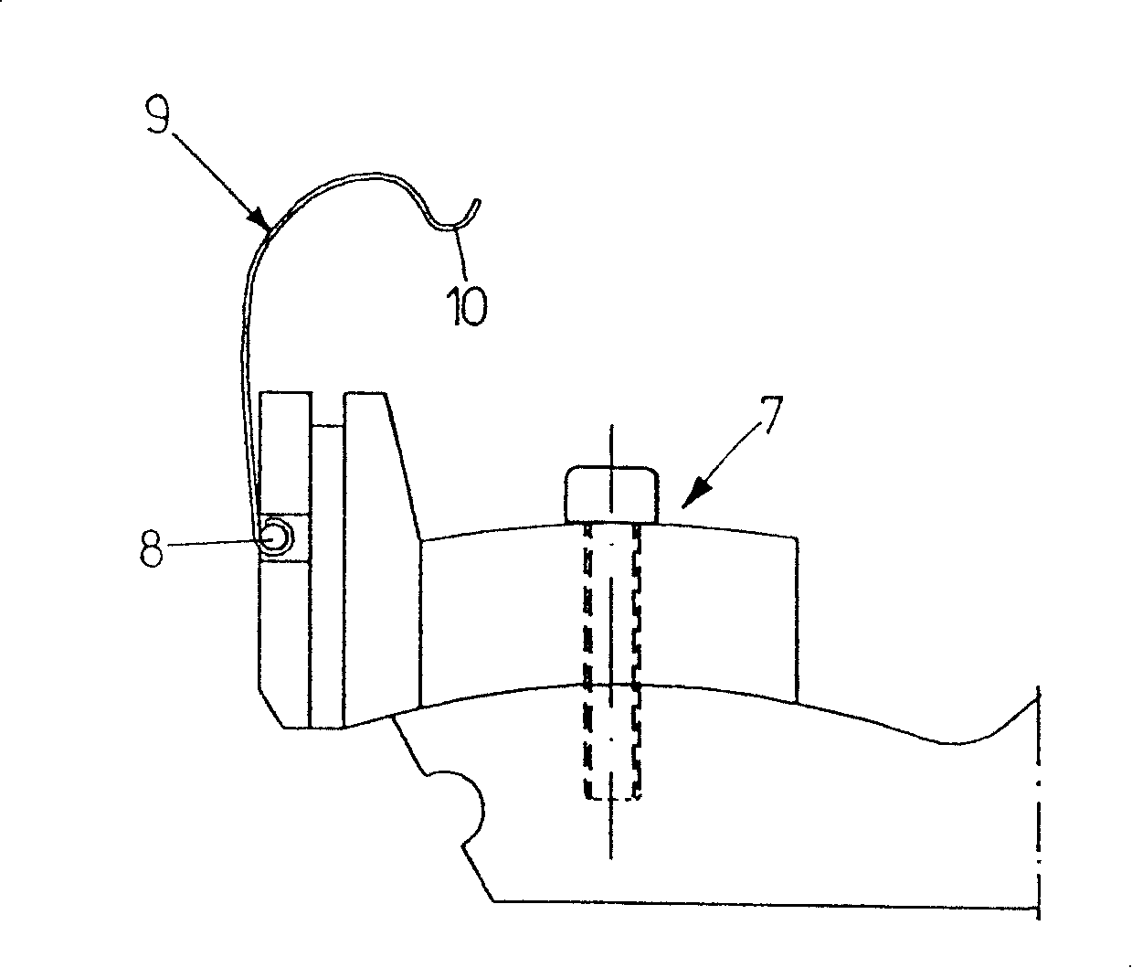
[0031] On the upper side of the top comb plate 2 is formed a fixing section 6 with a surface curved into approximately 1 / 4 of a circle. When the top comb 1 is loaded into the top comb bracket 7 on one side of the comber, the fixed section 6 is pressed by a fixed clamp 9 that can be rotatably supported around the shaft 8, wherein an elbow 10 on the end of the fixed clamp 9 is engaged. Tightly on the inner edge 11 of the fixed section 6. This is shown in more detail in section III in FIGS. 2 and 3 .

[0032] It can also be seen from this that although the shape of the fastening section 6 is precisely given in relation to production, it differs from the shape of the fastening clip 9, so that the fastening clip fits point-like or linearly on the fastening section at points 12 and 13. 6, la...


PUM

PropertyMeasurementUnit
Shore hardnessaaaaaaaaaa
hardnessaaaaaaaaaa

Abstract

The invention relates to a top comb (1) for a textile combing machine, whereby the top comb (1) comprises a top comb plate (2), on the base body of which a pin stripe (3) may be fixed. A retaining section (6) is embodied on the upper face of the base body (18), by means of which the top comb (1) may be fixed thereto with a retainer clamp (9) of a corresponding top comb holder (7). According to the invention, a wear protector is arranged between top comb (1) and top comb holder (7), in particular a plastic with good stability and good surface friction properties.

Description

technical field [0001] The invention relates to a top comb and a top comb support for a textile combing machine, wherein the top comb has a top comb plate on which a needle strip can be fixed, wherein a fixed section is formed on the upper side of the base body, and the top comb This fastening section can be fastened to the support by means of a fastening clip of the top comb support. Background technique [0002] The top comb of the textile combing machine performs an approximately elliptical motion and is thereby and constantly subjected to varying acceleration forces due to its insertion into the fiber strip to be carded, which together with the gravity of the top comb itself causes the top comb and the top comb to High mechanical load on the mounting surface on the top comb support. This problem is always serious because the cycle times of modern combers are constantly increasing. [0003] Conventional top combs are drawn from aluminum and therefore have a precisely di...

Claims


Application Information

Patent Timeline
Patent Type & Authority Patents(China)
IPC IPC(8): D01G19/10
CPCD01G19/10
Inventor E·多尔F·亨宁格H·赫布斯特
Owner STAEDTLER & UHL
Why Eureka
Try Eureka