Supercharge Your Innovation With Domain-Expert AI Agents!

Piston for an internal combustion engine

一种内燃机、活塞的技术,应用在内燃机活塞领域,能够解决耗费等问题

Inactive Publication Date: 2008-07-30
MAHLE GMBH
View PDF7 Cites 0 Cited by
  • Summary
  • Abstract
  • Description
  • Claims
  • Application Information

AI Technical Summary

Problems solved by technology

[0003] Here, in the very complex assembly process of the known piston, the cooling channel cover must first be pushed to the upper part of the piston facing away from the piston before the ring nut can be screwed into the projection so that the cooling channel cover can be screwed on. top bottom side

Method used


Image

  • Piston for an internal combustion engine
  • Piston for an internal combustion engine
  • Piston for an internal combustion engine

Examples


Embodiment Construction

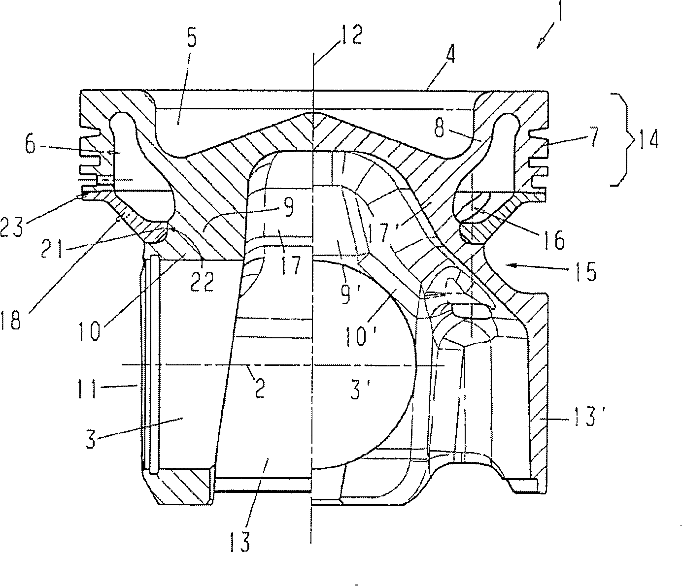
[0041] figure 1 is a one-piece piston 1 of an internal combustion engine shown in a cross-sectional view consisting of two halves, wherein the left half represents a cross-section of the piston 1 along a longitudinal axis 2 of the piston pin hole 3, the right half Shows a longitudinal section of the piston 1 staggered by 90°. The piston 1 is made of steel and has a combustion chamber 5 in the region of the piston crown 4 . An annular cooling channel 6 is arranged in the radially outer region of the piston crown 4, the radially outer boundary of said cooling channel is bounded by a ring wall 7 which conforms to the shape of the piston crown 4, the cooling channel's The radial inner boundary is bounded partly by a ring rib 8, partly by a piston pin support 9, 9' and partly by a piston skirt connection 17, 17'. The ring wall 7 serves here as a piston ring carrier.

[0042] Each piston pin seat 10 , 10 ′ with a piston pin hole 3 , 3 ′ conforms to the outer shape of the piston c...


PUM


Abstract

The invention relates to a single-pieced piston (1) for an internal combustion engine. Said piston comprises an annular shaped cooling channel (6) disposed in the edge area of the base of the piston (4). Said cooling channel is closed by a cooling channel cover (18), towards the side of the bolt hubs (10,10') consisting of at least two semi-circular covering elements (19, 20) and said cover, is embodied as a supporting element. The external edge (23) of the cover supports the bolt hub side front surface of the annular wall (7).

Description

technical field [0001] The invention relates to a piston of an internal combustion engine. Background technique [0002] A multi-part reciprocating fuel engine piston is known from DE 33 38 419, which piston has a piston crown, an annular cooling channel being arranged in the peripheral region of the piston crown. The radially outer boundary of the cooling channel is bounded by a ring wall which conforms to the contour of the peripheral region of the piston crown and serves as a seat for the piston ring. The cooling channel is closed on the side of the piston pin seat by an annular cooling channel covering formed as a support element, the inner edge of which is enclosed by an annular The nut is supported, which is screwed onto an annular projection which conforms to the contour of the piston crown, and the outer edge of the cover supports the ring wall via its end face on the piston pin seat side. [0003] Here, in the very complex assembly process of the known piston, the...

Claims


Application Information

Patent Timeline
Patent Type & Authority Patents(China)
IPC IPC(8): F02F3/22
CPCF02F3/22F02F2003/0007F16J1/00
Inventor 赖纳·沙普
Owner MAHLE GMBH
Features
  • R&D
  • Intellectual Property
  • Life Sciences
  • Materials
  • Tech Scout
  • Unparalleled Data Quality
  • Higher Quality Content
  • 60% Fewer Hallucinations
Learn More