
Automatic pressure reducing flow stable valve

An automatic decompression and steady flow valve technology, which is applied in fluid pressure control without auxiliary power, safety valve, balance valve, etc., can solve the problem of unstable water pressure, affecting the normal use of water heaters, hot water temperature fluctuating high and low, etc. problem, to achieve the effect of increasing the gap

Inactive Publication Date: 2008-08-06
王海平
View PDF9 Cites 0 Cited by
  • Summary
  • Abstract
  • Description
  • Claims
  • Application Information

AI Technical Summary

Problems solved by technology

The level of the water temperature is generally achieved by adjusting the channel area of ​​the valve to change the flow of water. However, because the water pressure in the public water pipe network is not stable, the position of the valve adjustment knob is fixed. The size is also not stable, which directly causes the temperature of the hot water to fluctuate, causing users to frequently adjust the valve without much trouble
When the water pressure of the public water pipe network fluctuates too much, it may even affect the normal use of the water heater

Method used


Image

  • Automatic pressure reducing flow stable valve

Examples


Embodiment

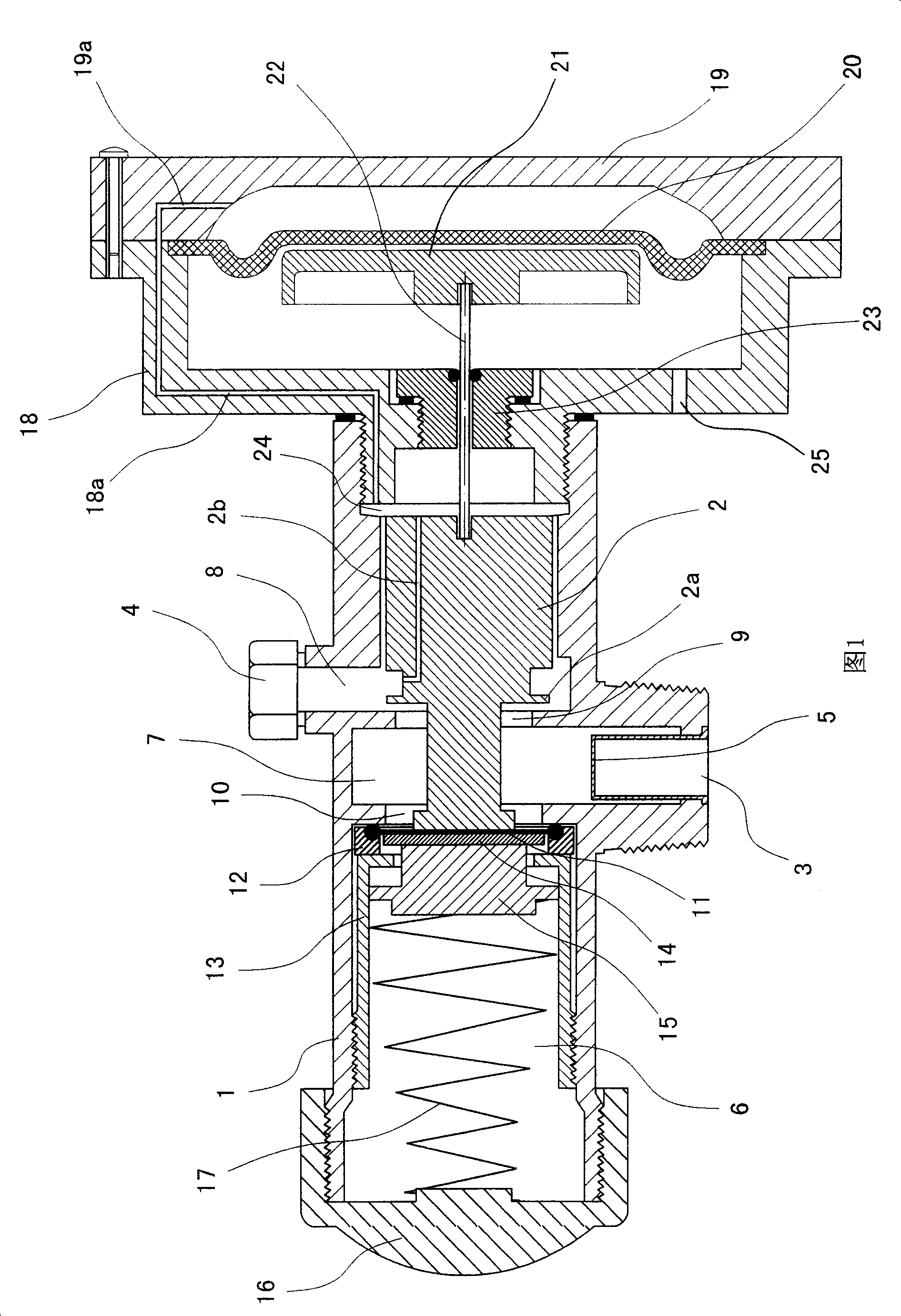
[0020] As shown in Figure 1, it is a preferred embodiment of the present invention. As shown in the figure, the automatic decompression and steady flow valve of this embodiment has a valve body 1 and a valve core 2 , and a fluid inlet 3 and a fluid outlet 4 are provided in the middle of the valve body 1 . A filter screen 5 is provided at the fluid inlet 3 . The inner cavity of the valve body 1 is provided with a spring cavity 6 , a fluid inlet cavity 7 corresponding to the fluid inlet 3 and a fluid outlet cavity 8 corresponding to the fluid outlet 4 from left to right. A flow-restricting hole 9 is provided between the fluid inlet 7 and the fluid outlet 8 , and a through-hole 10 is provided between the spring chamber 6 and the fluid inlet 7 , and the diameter of the through-hole 10 is larger than that of the flow-restricting hole 9 . The valve core 2 extends from the right end of the valve body 1 into the inner cavity of the valve body 1 and is assembled in the inner cavity of...


PUM


Abstract

The disclosed steady flow valve includes valve body, valve core, liquid inlet, and liquid outlet. Characters are that spring cavity, inlet cavity and outlet cavity is setup in inner cavity of valve body; current limiting hole is setup between inlet cavity and outlet cavity; a through hole is setup between spring cavity and inlet cavity, and area of the through hole is larger than area of the current limiting hole; elastic seal membrane piece is at left side of the through hole, moveable piston withstands left side of the elastic seal membrane piece, and compression spring is at left side of the moveable piston; push rod withstands right end of the valve core; the seal membrane piece provides thrust force for the push rod, and thrust force of the seal membrane piece is from liquid pressure at liquid outlet cavity. The steady flow valve reduces pressure at output end and stabilizes flux. The valve is suitable to matching water heater and equipment needed decompression and steady flow.

Description

technical field [0001] The invention relates to a valve, in particular to an automatic pressure-reducing and steady-flow valve with functions of reducing outlet pressure and stabilizing flow. Background technique [0002] The function of ordinary valves is to open and close fluid pipelines, and its flow control is generally controlled by adjusting the opening of the valve. But in actual use, the fluid pressure at the inlet end of the valve is usually unstable, so its flow rate is also unstable. Moreover, in most applications, the fluid pressure at the inlet end of the valve or the fluid pressure of the fluid supply pipe network is usually higher than that of the fluid supply network. It is easy to use directly, and the output pressure at the outlet of ordinary valves is usually directly related to the flow rate. Specifically, the larger the flow rate, the smaller the decompression effect, and the larger the output pressure, and vice versa. Therefore, ordinary valves cannot ...

Claims


Application Information

Patent Timeline
Patent Type & Authority Patents(China)
IPC IPC(8): F16K17/04G05D16/06
Inventor 王海平
Owner 王海平
Learn More