Vacuum filter

A filtration device and vacuum technology, which is applied in filtration and separation, fixed filter element filters, mobile filter element filters, etc., can solve the problems of reducing the interval between vacuum hoses, increasing the number of connecting parts, and difficult to ensure storage space, etc. The effect of suppressing tilt, achieving stability, and suppressing obstacles to movement

Active Publication Date: 2008-08-13
TSUKISHIMA KIKAI CO LTD
View PDF8 Cites 0 Cited by
  • Summary
  • Abstract
  • Description
  • Claims
  • Application Information

AI Technical Summary

Problems solved by technology

Therefore, the vacuum carriage is subjected to a force in a direction intersecting with its moving direction, and it is difficult to realize the stability of the straight forward movement of the vacuum carriage.
[0006] In this case, for example, when supporting wheels that are connected from below to support the vacuum carrier are arranged at both ends in the width direction of the vacuum carrier, the amount of wear of the supporting wheels and the like is different for each end in the width direction. The so-called uneven wear causes the vacuum bracket to tilt, and the filter cloth is easy to snake and move, which may hinder the movement of the vacuum bracket.
In addition, for example, where guides are provided that limit the sides of the vacuum carriage in its direction of movement, due to the above-mentioned inclination of the vacuum carriage, the sides of the vacuum carriage abut against the guides, making it easier to Create conditions that impede the movement of the vacuum carriage
[0007] In particular, in the case of the large-scale vacuum filtration device, since the amount of filtrate recovered from the slurry is increased, and it is necessary to uniformly generate the vacuum suction force on the slurry in the width direction of the vacuum bracket, although sometimes it is not possible to The vacuum hose is not made to have a large diameter, but the force acting on the vacuum bracket due to the curved shape of the vacuum hose also becomes larger, so the problem of hindering the movement of the vacuum hose becomes serious
Moreover, in this way, as the diameter of the vacuum hose becomes larger, it is installed in a bent state as described above, and the radius of the bend cannot be increased, so there is a problem that it is difficult to secure a space for storing such a vacuum hose.
[0008] In addition, a plurality of vacuum carriages are provided along the moving direction, and in the structure in which the connecting member is provided on each of these vacuum carriages, due to the increase in the diameter of the vacuum hose, the front and back are reversed in the moving direction. The distance between adjacent vacuum hoses becomes smaller, and the maintenance man-hours under the vacuum bracket may increase
On the other hand, if the number of joints is increased to prevent the diameter of the vacuum hose from becoming larger, the number of vacuum hoses will also increase, resulting in interference between these vacuum hoses, or interference between the vacuum hose and the above-mentioned support wheels. bring about problems

Method used


Image

  • Vacuum filter
  • Vacuum filter
  • Vacuum filter

Examples


Embodiment Construction

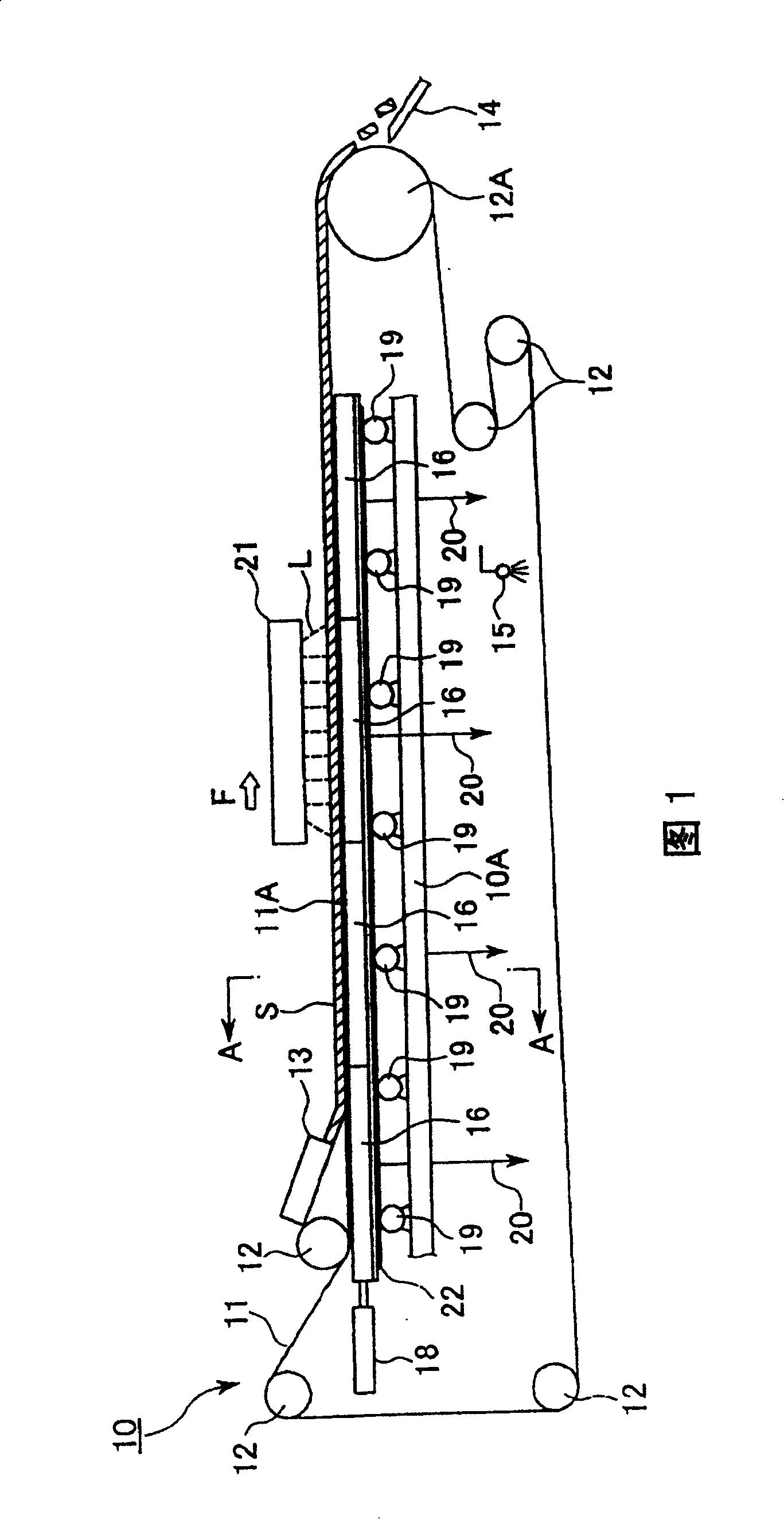
[0022] Figure 1~ Figure 5 It is a figure which shows one embodiment of this invention. In the vacuum filter device of this embodiment, in the device main body 10, the endless belt-shaped filter cloth 11 is wound on a plurality of rollers 12 in sequence, and the upper part of the filter cloth 11 is arranged so as to extend horizontally. It becomes the filter part 11A. And, on one end side (the right side in FIG. 1 ) of this filter part 11A, the roller 12A on which the filter cloth 11A is wound is connected to a driving device not shown in the figure, and the roller 12A is driven by the driving device to turn to the drawing. Rotating clockwise, the filter cloth 11 is also continuously driven around the rollers 12..., and with this, the filter part 11A of the filter cloth 11 moves continuously in the moving direction shown by the arrow F in the figure.

[0023] On the other end side (left side in FIG. 1 ) of the filter portion 11A of the filter cloth 11 , that is, above the re...


PUM


Abstract

To provide a vacuum filter device capable of allowing a vacuum tray to travel well and certainly. In the vacuum filter device constituted so that the vacuum tray 16 connected to a vacuum suction device through a connector is provided under filter cloth provided to a device main body so as to be capable of traveling almost horizontally and the slurry supplied to the filter cloth is sucked under vacuum by the vacuum tray 16 through the filter cloth, the vacuum tray 16 is made possible to advance and retreat in the traveling direction of the filter cloth and a plurality of connectors are provided. Each of the connectors has vacuum hoses 20B having elasticity and the vacuum hoses 20B are arranged so as to extend on mutually opposite sides on the basis the central part in the width direction of the vacuum tray 16.

Description

technical field [0001] The present invention relates to a vacuum filtration device that vacuum-suctions slurry supplied to a filter cloth that can move substantially horizontally by a vacuum bracket provided under the filter cloth to perform filtration. Background technique [0002] As this vacuum filter device, for example, in the following Japanese Patent Laid-Open No. 62-79817 and Japanese Patent Laid-Open No. 7-148404, etc., the following schemes are proposed, in which the filter cloth is arranged in an annular coil and arranged on the main body of the device. It can move continuously around its circumferential direction on multiple rollers on the upper part of the device. On the part where the filter cloth on the upper part of the main body of the device moves horizontally, it can advance and retreat under the filter cloth with a predetermined stroke in the moving direction of the filter cloth. A plurality of vacuum brackets respectively connected to the vacuum suction ...

Claims


Application Information

Patent Timeline
Patent Type & Authority Patents(China)
IPC IPC(8): B01D33/04B01D29/09
CPCB01D33/00B01D33/056B01D33/44
Inventor 岩崎修二小岛久史
Owner TSUKISHIMA KIKAI CO LTD
Why Eureka
Try Eureka