Electro-optical modulator working point control device and method

An electro-optic modulator and control device technology, applied in the field of optical transmission network, can solve the problems of limiting control loop accuracy and complex control circuit, and achieve fast response speed, good control effect and simple circuit

Active Publication Date: 2013-11-27
WUHAN TELECOMM DEVICES
View PDF5 Cites 9 Cited by
  • Summary
  • Abstract
  • Description
  • Claims
  • Application Information

AI Technical Summary

Problems solved by technology

However, the full hardware control makes the control circuit very complicated, time-division multiplexing controls 6 bias operating point voltages, and the temperature stability of circuit devices also limits the accuracy of the entire control loop

Method used


Image

  • Electro-optical modulator working point control device and method
  • Electro-optical modulator working point control device and method
  • Electro-optical modulator working point control device and method

Examples


Embodiment Construction

[0038] In order to facilitate a further understanding of the structure, method and achieved effects of the present invention, preferred embodiments are described in detail below in conjunction with the accompanying drawings.

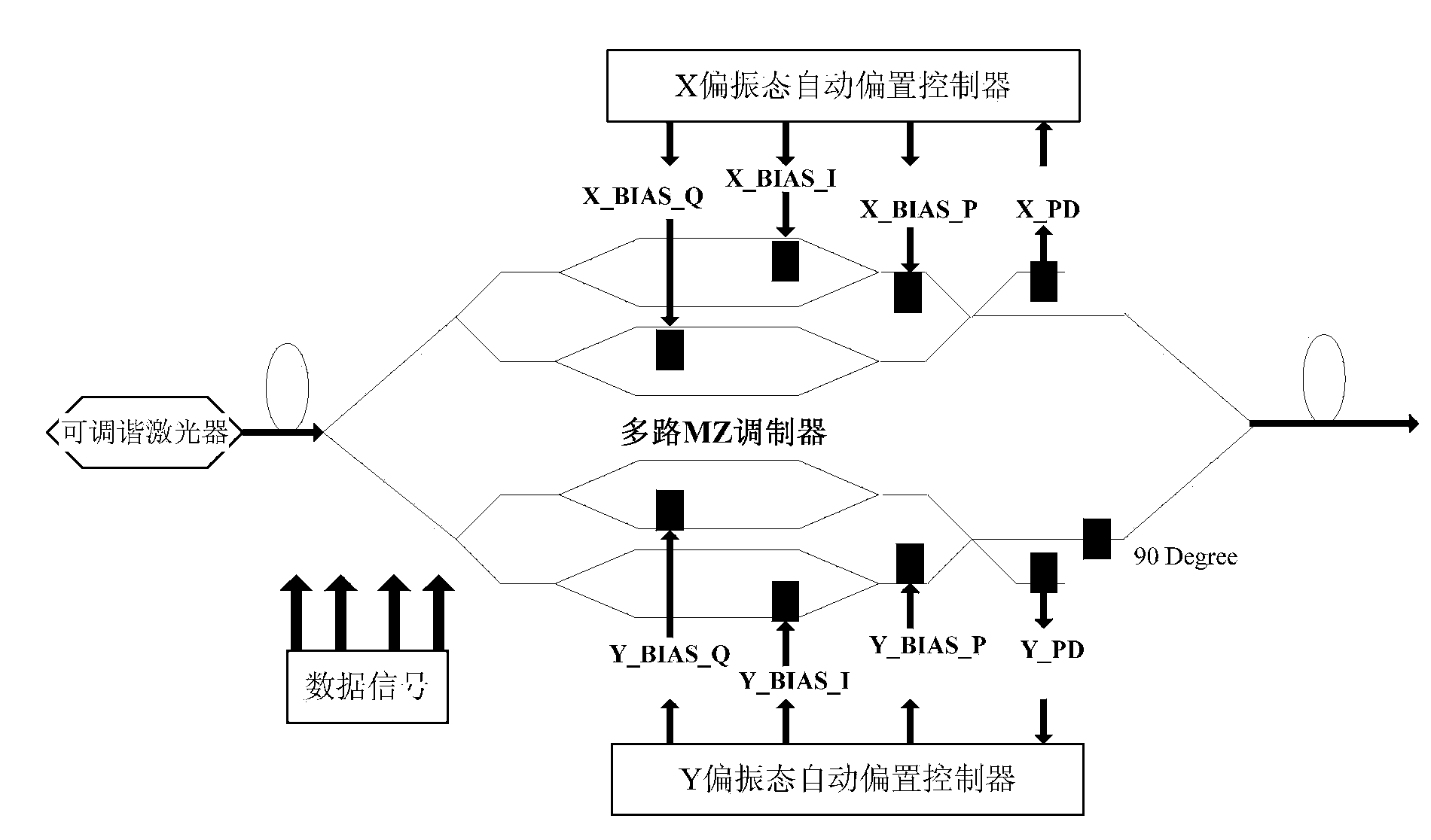
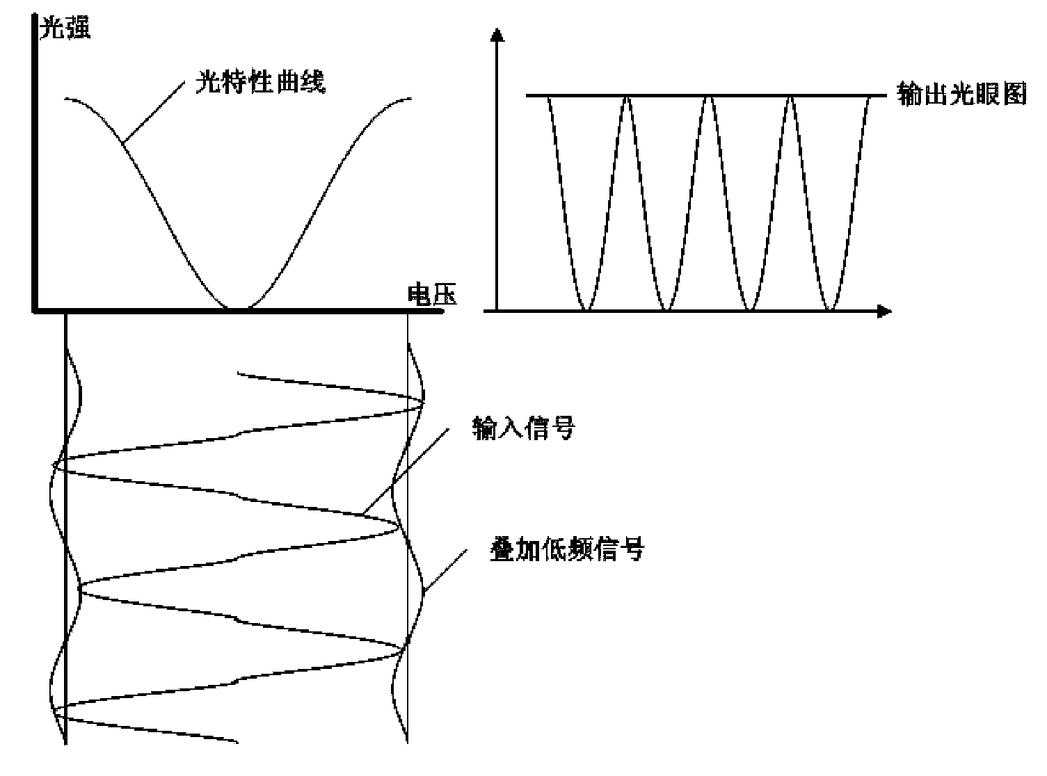
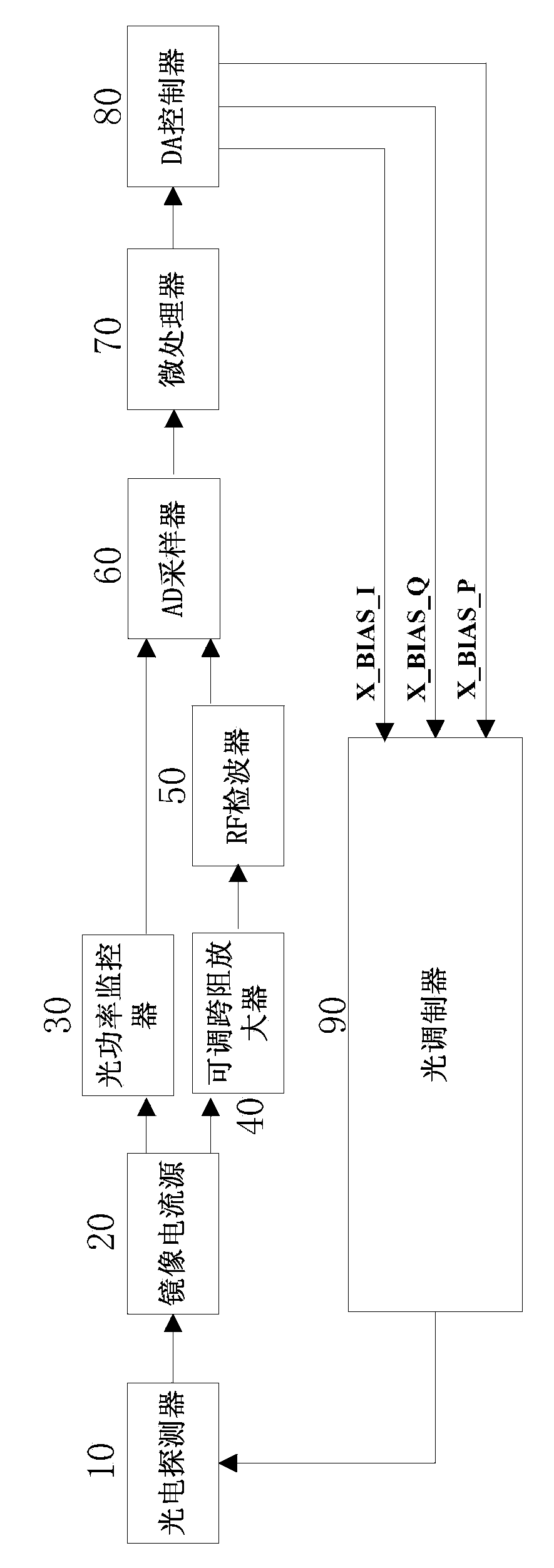
[0039] According to the application requirements, each channel of the polarization coherent modulator is required to work at the maximum output optical power point, that is, the middle level of the data signal is located at the minimum point of the optical characteristic curve, such as figure 2 Shown, while the pai / 2 optical phase shift corresponds to the RF (radio frequency) signal minimum point. The photocurrent signal is detected by the PD (photodetector) of the modulator and the signal is mirrored, and the optical power is monitored all the way, and the monitored amount is input to the MCU (microprocessor) to obtain the control amount by software algorithm, and then through the DA (digital-analog converter) to adjust the I / Q bias of the modulator, a...


PUM


Abstract

The invention discloses an electro-optical modulator working point control device and method. The control device comprises a photoelectric detector, an image current source, an optical power monitor, an adjustable trans-impedance amplifier, an RF (radio frequency) detector, an AD (analog to digital) sampler, a microprocessor, a DA (digital to analog) controller and an optical modulator. The microprocessor acquires optical power monitoring signals and RF power signals in real time and calculates maximum value of optical power and minimum value of RF power so as to control optimal working points of the modulator. By the control device and method, the problems that hardware control circuits of MZ modulator offset points are complex and low in control precision and the like in the prior art, and simple circuit, good control effect and fast response are achieved.

Description

technical field [0001] The invention relates to the field of optical transmission networks, in particular to a working point control device and a control method applied to polarization coherent phase modulators. Background technique [0002] Due to the rapid development of IPTV (Interactive Network Television), HDTV (High Definition Television), VoD (Video On Demand, video on demand) and mobile broadband services, especially Internet-based video applications and P2P (peer-to-peer With the rapid development of network) applications, the business traffic of the operator's backbone network continues to grow. In order to meet the requirements of large-capacity network bandwidth, a polarization coherent phase modulation technology is currently required for 100G bit / s long-distance transmission in the field of optical fiber communication. For the current photoelectric phase modulation, the MZ (Mach-Zehnder) modulator is generally used to realize the niobium lithium oxide material....

Claims


Application Information

Patent Timeline
Patent Type & Authority Applications(China)
IPC IPC(8): G05F1/46G02F1/01
Inventor 蔡亮胡毅邹晖杨瑾马建国杨俊麒
Owner WUHAN TELECOMM DEVICES
Why Eureka
Try Eureka