Positioning fastener of manual tool

A technology of positioning and hand tools, which is applied in the manufacture of tools, wrenches, screwdrivers, etc., can solve the problems of limited service life, limited effect of structural clamping, difficulty in achieving high positioning effect, etc., and achieve stable and reliable joint structure and safe joint sex high effect

Inactive Publication Date: 2008-08-13
陈泰佐
View PDF10 Cites 0 Cited by
  • Summary
  • Abstract
  • Description
  • Claims
  • Application Information

AI Technical Summary

Problems solved by technology

[0003] For example, China Taiwan No. 87210568 "Improvement of the Sleeve Locking Structure of the Ratchet Wrench", it is provided with a groove on the joint to cover an O-ring, by virtue of the elasticity of the O-ring The end surface opposite to the tool is stuck, the effect of such a structure is very limited, and the material of the O-ring is prone to adverse changes, hardening or becoming brittle, and the service life is limited; therefore, some operators change it to a C-shaped buckle However, it is a loose fit, so when the joint is connected to the tool, the C-shaped buckle is prone to improper displacement, so that the clamping with the tool cannot be positioned accurately, and it is difficult to achieve a high positioning effect. Purpose: Another company improves the structure of its simple C-shaped buckle, and improves the effect of locking and positioning with different shapes, among them, such as Taiwan, China No. 90220753 "Clamping Device for Tools (2) 』The new patent case, please refer to Figure 6, which is to clamp the two free ends of the fastener 90 on the slot 910 of the joint 91, and at least two inwardly retracted stoppers 900 are provided at the periphery And at least one protruding catch part 901, clamped against the draw-in groove 910 by the limit part 900, and the catch part 901 protrudes outside the draw-in groove 910; When the slot 910 is on, the locking member 90 will still rotate in the slot 910, which is not a fixed structure. Therefore, the position where the locking part 901 of the locking member 90 is exposed to the slot is uncertain, and it is locked at one point. When it is used, it will produce improper offset, so that its clamping cannot be kept in the most stable state, so it is necessary to improve

Method used


Image

  • Positioning fastener of manual tool
  • Positioning fastener of manual tool
  • Positioning fastener of manual tool

Examples


Embodiment Construction

[0023] In order to further understand the structure, characteristics and other purposes of the present invention, the following preferred embodiments are attached with drawings for detailed description as follows, but the embodiments described in this illustration are for illustration purposes, not for patent applications The only limitation on .

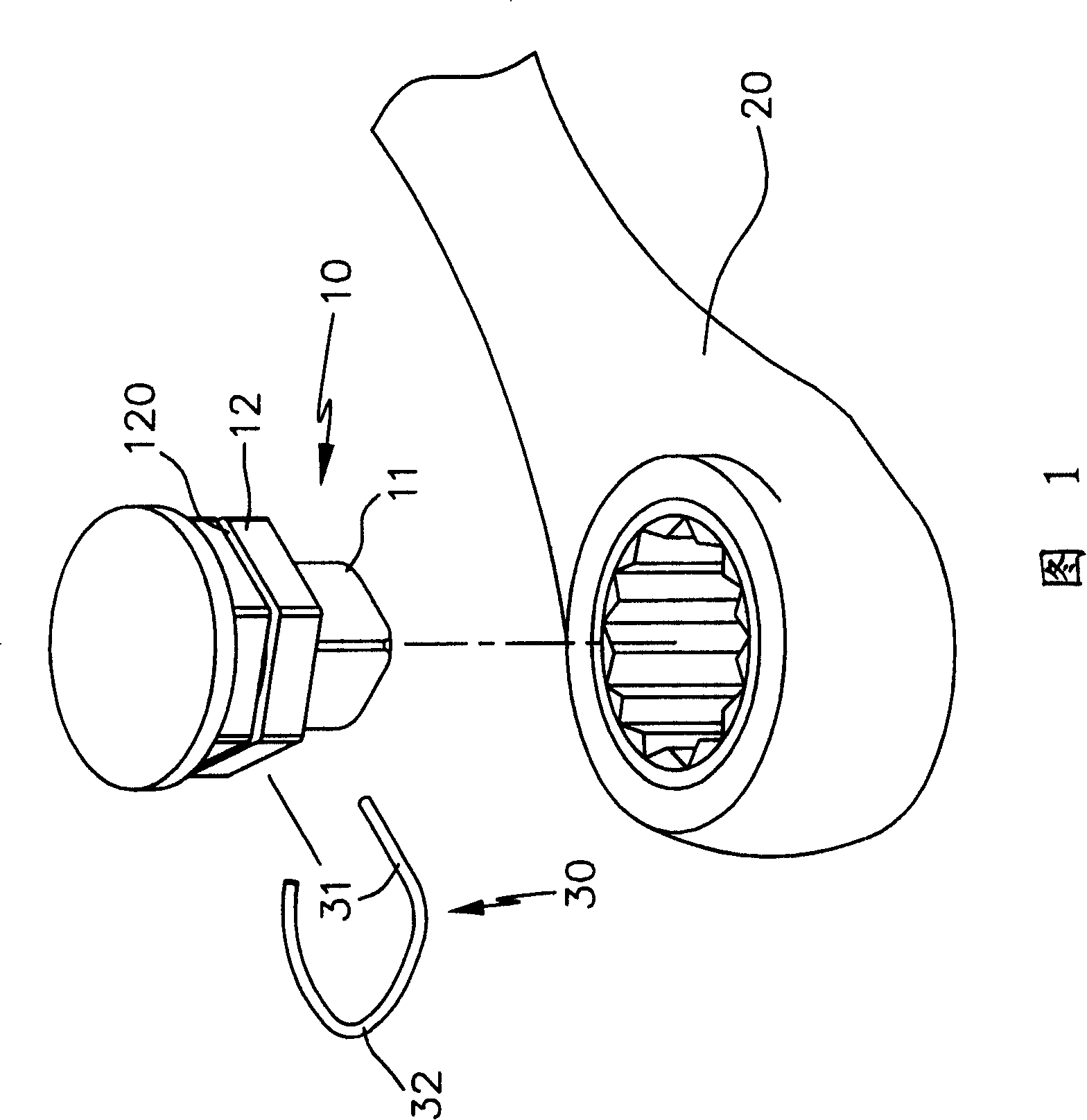
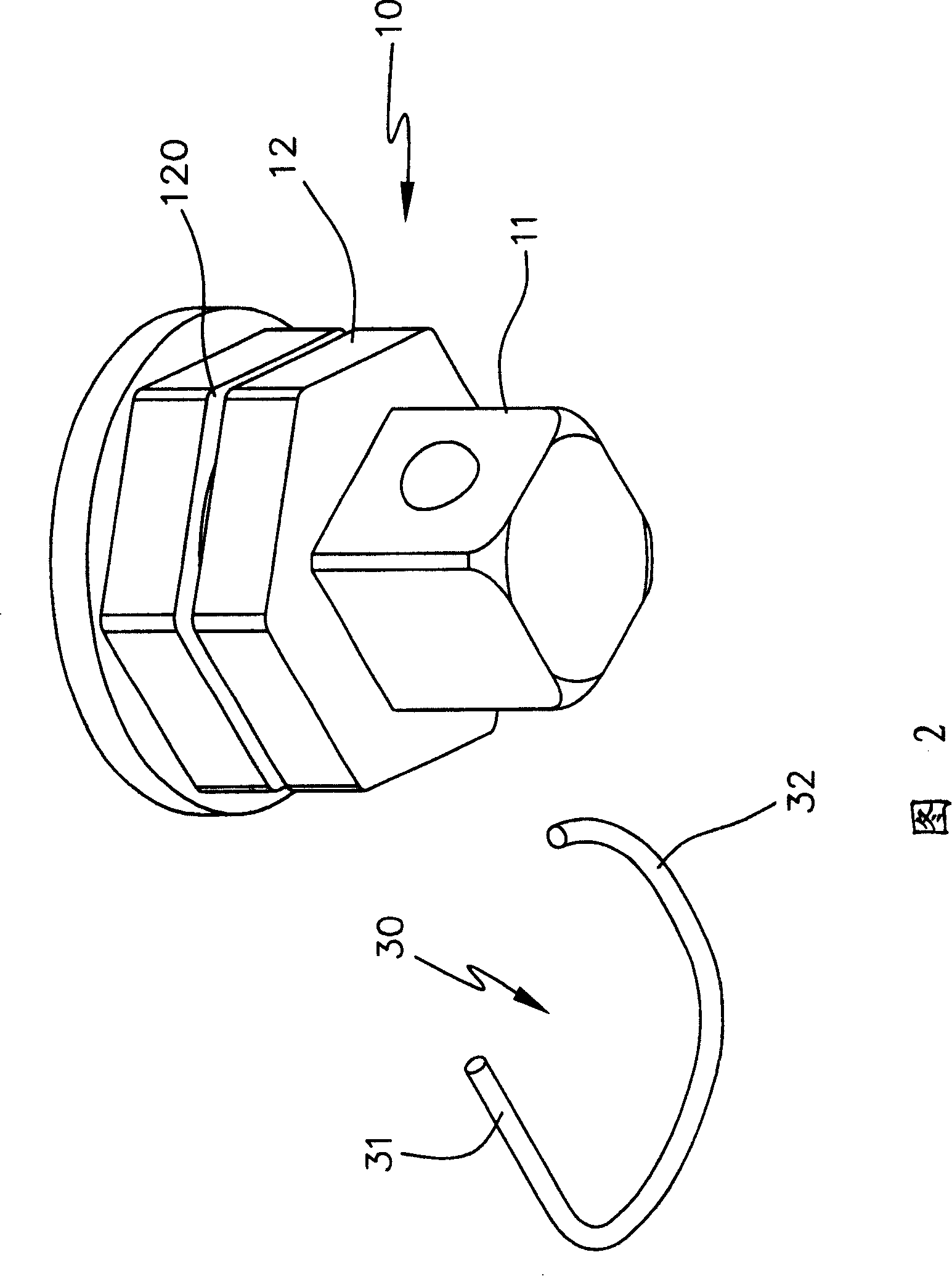
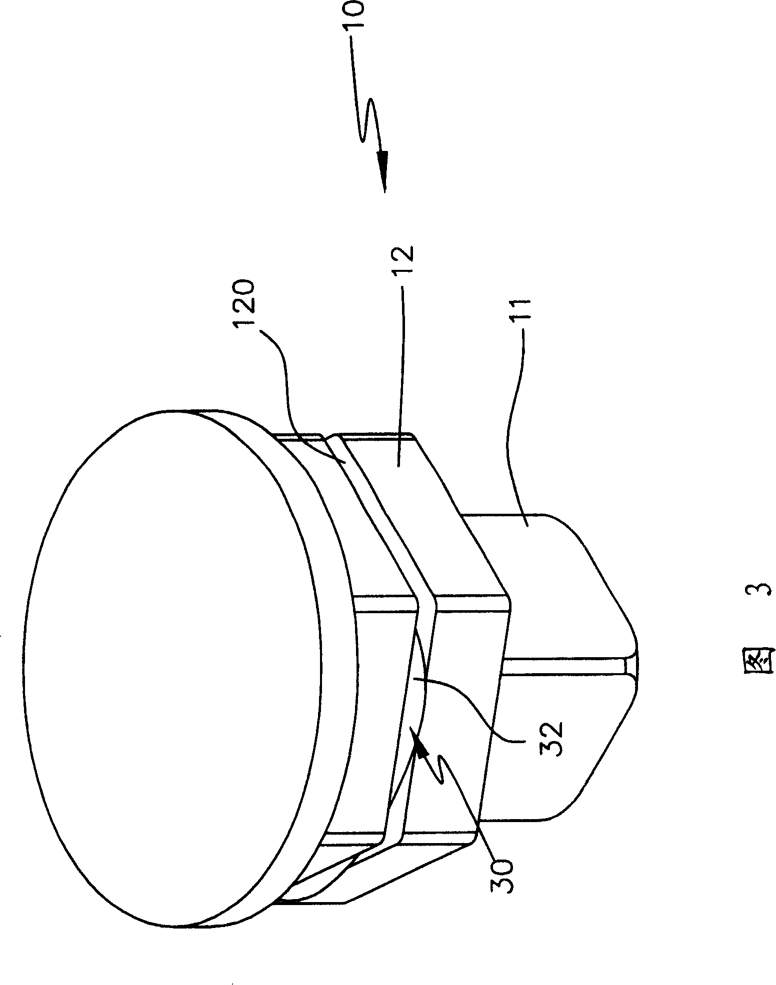
[0024] Please refer to Figs. 1-4, the joint 10 of the present invention can be socketed with various tools 20, and its joint 10 has a driving end 11, and its driving end 11 is adjacent to a set of sleeves seated on the tool 20. Fitting portion 12, and the outer diameter of fitting portion 12 is recessed with a positioning groove 120, for an elastic semi-circular fastening member 30 to be snapped in and positioned, and partly protrudes from positioning groove 120 to match with the opposite tool 20 The end surface is elastically snapped and positioned.

[0025] Among them, the joint 10 mainly has a driving end 11 for driving other wo...


PUM


Abstract

A locating fastener for fastening a manual tool (spanner) at a fixed position has a jointer with a locating slot which has at least one turn-stopping with a locating slot which has at least one turn-stopping part, and a fastener with at least one group of turn-stopping parts at its one end and at least one group of elastic fastening parts at its another end.

Description

Technical field: [0001] The invention relates to a hand tool positioning type clamping device. Background technique: [0002] At present, the structure of joints and hand tools has been developed very maturely, and many structures have been applied for patents, including: [0003] For example, China Taiwan No. 87210568 "Improvement of the Sleeve Locking Structure of the Ratchet Wrench", it is provided with a groove on the joint to cover an O-ring, by virtue of the elasticity of the O-ring The end surface opposite to the tool is stuck, the effect of such a structure is very limited, and the material of the O-ring is prone to adverse changes, hardening or becoming brittle, and the service life is limited; therefore, some operators change it to a C-shaped buckle However, it is a loose fit, so when the joint is connected to the tool, the C-shaped buckle is prone to improper displacement, so that the clamping with the tool cannot be positioned accurately, and it is difficult to ...

Claims


Application Information

Patent Timeline
Patent Type & Authority Patents(China)
IPC IPC(8): B25B23/00
Inventor 陈泰佐
Owner 陈泰佐
Why Eureka
Try Eureka